
Anode and method of manufacturing the same, and battery and method of manufacturing the same

a technology of anode and battery, applied in the direction of isotope separation, electrolysis, primary cells, etc., can solve the problem of insufficient cycle characteristics, and achieve the effect of improving charge-discharge efficiency and chemical stability

Active Publication Date: 2009-04-09
MURATA MFG CO LTD
View PDF3 Cites 47 Cited by
  • Summary
  • Abstract
  • Description
  • Claims
  • Application Information

AI Technical Summary

Benefits of technology

[0007]In view of the foregoing, it is an object of the invention to provide an anode capable of improving charge-discharge efficiency and a method of manufacturing the anode, and a battery using the anode, and a method of manufacturing the battery.
[0011]In the first anode and the first battery according to the invention, the oxide-containing film is formed in a region in contact with the electrolyte of the surface of each anode active material particle by a liquid-phase method, so the region in contact with the electrolyte of the surface of each anode active material particle can be uniformly covered with the oxide-containing film, and chemical stability can be improved. Therefore, in the battery using the anode, charge-discharge efficiency can be improved.
[0012]In the method of manufacturing an anode and the method of manufacturing a battery according to the invention, the oxide-containing film is formed by a liquid-phase method, so the oxide-containing film can be formed in the interior, which cannot be not covered with the oxide-containing film by a vapor-phase method, of the anode active material layer, and the anode according to the invention can be easily manufactured.
[0015]In the second anode according to the invention, a coating film including an oxide of at least one kind selected from the group consisting of silicon, germanium and tin and a halide of at least one kind selected from the group consisting of silicon, germanium and tin is arranged on at least a part of a surface of the anode active material, so chemical stability can be improved. Therefore, in the second battery using the second anode, charge-discharge efficiency can be improved.

Problems solved by technology

However, there are an issue that properties of a coating film formed by air oxidation are poor and an issue that anode active material particles are not sufficiently covered with a coating film formed by a vapor-phase method, thereby sufficient cycle characteristics cannot be obtained, so a further improvement is desired.

Method used


Image

  • Anode and method of manufacturing the same, and battery and method of manufacturing the same
  • Anode and method of manufacturing the same, and battery and method of manufacturing the same
  • Anode and method of manufacturing the same, and battery and method of manufacturing the same

Examples


first embodiment

(First Type Battery)

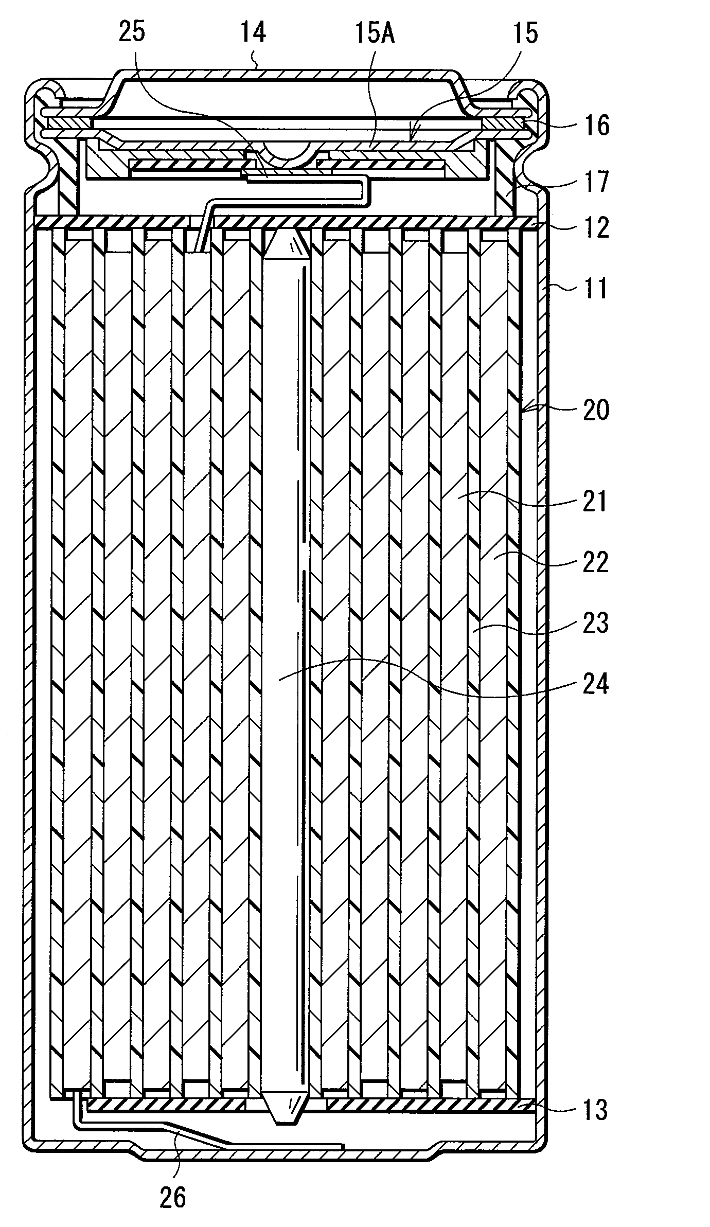
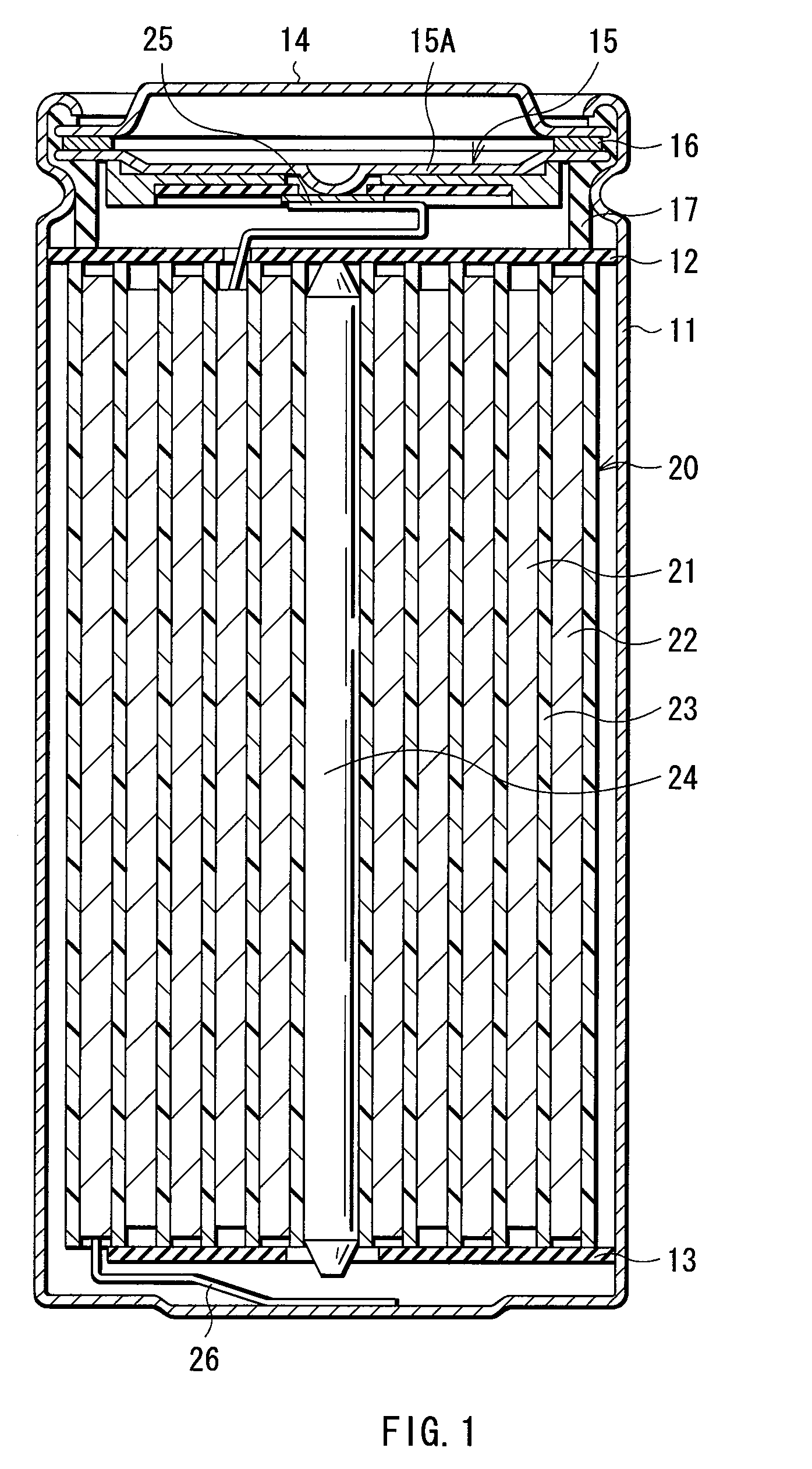
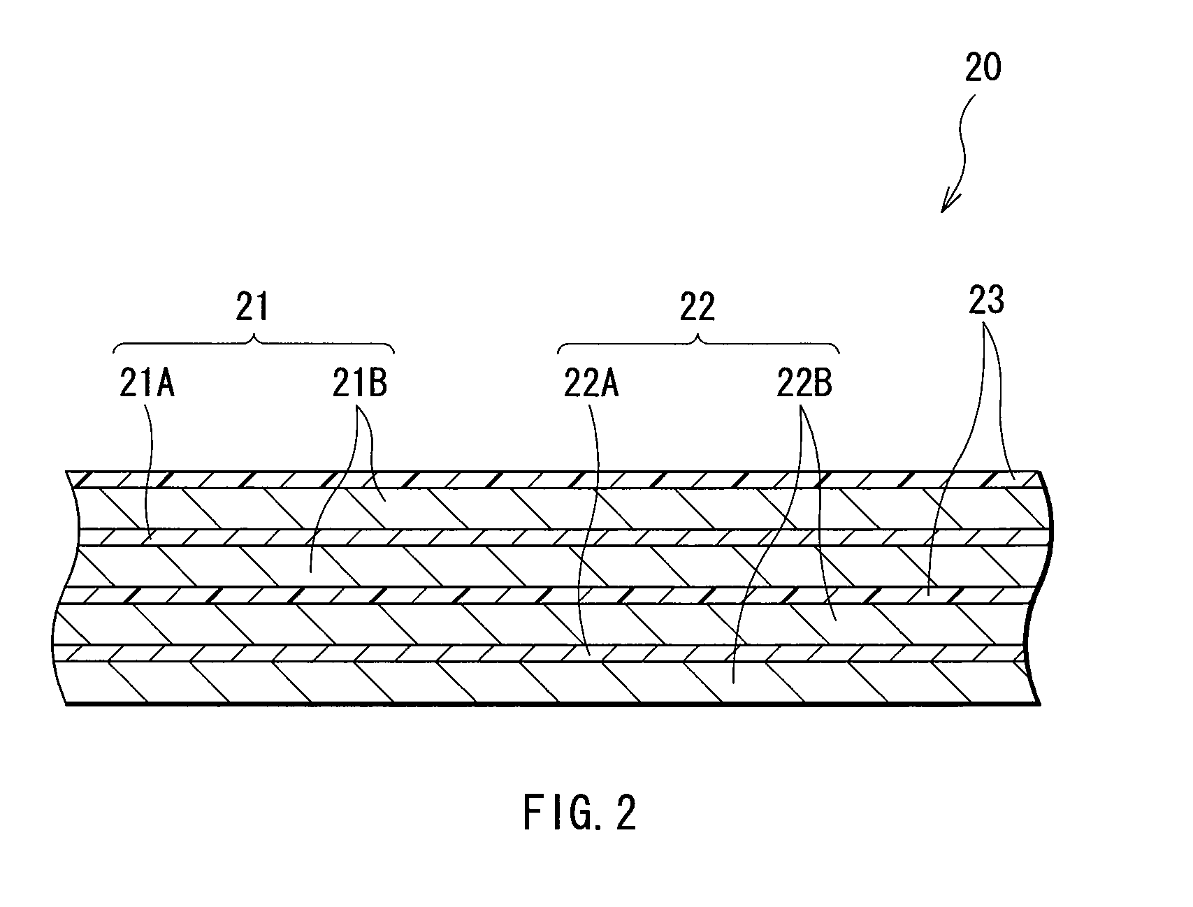
[0026]FIG. 1 shows a sectional configuration of a first type secondary battery according to a first embodiment of the invention. The secondary battery is a so-called cylindrical type, and includes a spirally wound electrode body 20 which includes a strip-shaped cathode 21 and a strip-shaped anode 22 spirally wound with a separator 23 in between in a substantially hollow cylindrical-shaped battery can 11. The battery can 11 is made of, for example, nickel-plated iron, and an end portion of the battery can 11 is closed, and the other end portion thereof is opened. An electrolytic solution as a liquid electrolyte is injected into the battery can 11, and the separator 23 is impregnated with the electrolytic solution. Moreover, a pair of insulating plates 12 and 13 are arranged so that the spirally wound electrode body 20 is sandwiched therebetween in a direction perpendicular to a peripheral winding surface.

[0027]In the opened end portion of the battery can 11, a bat...

second embodiment

[0112]A secondary battery according to a second embodiment will be described below. The secondary battery according to the second embodiment has the same configuration, functions and effects as those in the first embodiment, and can be manufactured by the same method, except that the anodes 22 and 34 are formed by a vapor-phase method, a liquid-phase method or a firing method. Therefore, in the embodiment, FIGS. 1, 2, 3 and 4 are referred, and like components are denoted by like numerals as of the first embodiment, and will not be further described.

[0113]As in the case of the first embodiment, the anodes 22 and 34 have a configuration in which anode active material layers 22B and 34B are arranged on both sides of anode current collectors 22A and 34A, respectively. As in the case of the first embodiment, the anode active material layers 22B and 34B each include the anode active material including at least one of silicon and tin as an element. As in the case of the first embodiment, t...

third embodiment

[0116]A secondary battery according to a third embodiment of the invention will be described below. The secondary battery according to the third embodiment of the invention has the same configuration as that in the first embodiment, except for a part of the configurations of the anodes 22 and 34. Therefore, in the embodiment, FIGS. 1, 2, 3 and 4 are referred, and like components are denoted by like numerals as of the first embodiment, and will not be further described.

[0117]As in the case of the first embodiment, the anodes 22 and 34 have a configuration in which the anode active material layers 22B and 34B are arranged on both sides of the anode current collectors 22A and 34A having a pair of facing surfaces, respectively. The anode active material layers 22B and 34B each include the same anode active material as that in the first embodiment.

[0118]In the embodiment, a coating film including an oxide of at least one kind selected from silicon, germanium and tin, and a halide of at l...


PUM

PropertyMeasurementUnit
Thicknessaaaaaaaaaa
Thicknessaaaaaaaaaa
Currentaaaaaaaaaa

Abstract

An anode capable of improving charge-discharge efficiency, and a method of manufacturing the anode, and a battery using the anode are provided. An anode 22 has a configuration in which an anode active material layer 22B is arranged on an anode current collector 22A. The anode active material layer 22B includes anode active material particles made of an anode active material including at least one of silicon and tin as an element. An oxide-containing film including an oxide of at least one kind selected from the group consisting of silicon, germanium and tin is formed in a region in contact with an electrolytic solution of the surface of each anode active material particle by a liquid-phase method such as a liquid-phase deposition method. The region in contact with the electrolytic solution of the surface of each anode active material particle is covered with the oxide-containing film, thereby the chemical stability of the anode 22 is improved, and charge-discharge efficiency is improved. The thickness of the oxide-containing film is preferably within a range from 0.1 nm to 500 nm both inclusive.

Description

TECHNICAL FIELD[0001]The present invention relates to an anode including an anode active material which includes at least one of silicon (Si) and tin (Sn) as an element, and a method of manufacturing the anode, and a battery and a method of manufacturing the battery.BACKGROUND ART[0002]In recent years, a large number of portable electronic devices such as camcorders, digital still cameras, cellular phones, personal digital assistances and laptop computers have been emerged, and an attempt to reduce the size and the weight of them has been made. Accordingly, the development of lightweight secondary batteries capable of obtaining a high energy density as power sources for the electronic devices have been promoted. Among them, a lithium-ion secondary battery using a carbon material for an anode, a composite material of lithium (Li) and a transition metal for a cathode and a carbonate for an electrolytic solution has been widely put to practical use, because the lithium-ion secondary ba...

Claims


Application Information

Patent Timeline
IPC IPC(8): H01M4/52H01M4/131H01M4/134H01M4/139H01M4/48H01M4/485H01M10/052H01M10/36
CPCH01M4/13H01M2300/0034H01M4/134H01M4/139H01M4/366H01M4/38H01M4/485H01M10/052Y02E60/122H01M10/0567H01M10/0569H01M10/058H01M2004/027H01M2300/0028H01M4/131H01M4/386H01M4/387Y02E60/10Y02P70/50H01M4/483H01M10/0525H01M10/0587
Inventor YAMAGUCHI, HIROYUKIHORIUCHI, HIROSHIKAWASE, KENICHIKUBOTA, TADAHIKONAKAI, HIDEKIHIROSE, TAKAKAZU
Owner MURATA MFG CO LTD
Learn More