Rotating bearing analysis and monitoring system

a technology of rotating bearings and monitoring systems, applied in liquid/fluent solid measurement, instruments, machines/engines, etc., can solve the problems of affecting the widespread commercial use of the system, and affecting the quality of the system

Inactive Publication Date: 2009-04-09
DYNAMIC MEASUREMENT CONSULTANTS
View PDF43 Cites 76 Cited by
  • Summary
  • Abstract
  • Description
  • Claims
  • Application Information

AI Technical Summary

Benefits of technology

[0030]In another aspect of the invention, the method includes allowing the user to modify the acceptable degree

Problems solved by technology

In spite of its technical effectiveness, the nature and complexity of vibration data and the process of extracting predictive failure data has added to the cost of its implementation and impeded its widespread commercial use.
More importantly, the data is not quantified and interpretation of its meaning is often very subjective.
The loss of one or two highly trained personnel can disrupt or cripple a major maintenance program.
However, this technique has a weakness in that it often fails to detect subtle high frequency, low level bearing defects.
High level energy from shaft imbalance and misalignment often dominates the overall signal causing it to be insensitive to low energy bearing problems.
For this reason machinery bearing component failures often occur without warning, because this technique failed to provide adequate warning.
This spectrum analysis technique is very effective when used by an experienced maintenance practitioner, but not very effective in the hands of most untrained maintenance personnel.
The spectrum analyzers and other analysis devices required are complex and require highly specialized training.
The spectral data generated by such techniques is voluminous and cumbersome to store track and interpret.
More importantly, the technology assumes that bearing defects will produce discrete frequencies related to the ball and race geometries, which is not often the case.
This is often difficult to detect and identify by spectral freq

Method used


Image

  • Rotating bearing analysis and monitoring system
  • Rotating bearing analysis and monitoring system
  • Rotating bearing analysis and monitoring system

Examples


Embodiment Construction

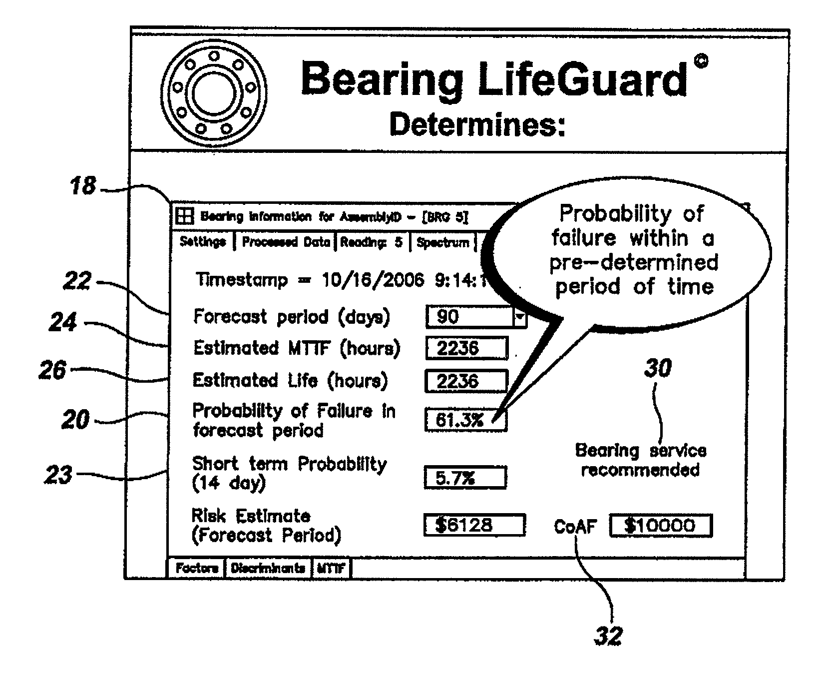
[0051]The present invention is directed to a system for obtaining and presenting information on rolling element bearing condition. Vibration data is obtained from one or more bearings, which may be distributed throughout a production facility on multiple machines. The vibration data for each bearing is stored and analyzed to determine a degraded condition factor BD for the bearing from the vibration data.

[0052]The degraded condition factor BD is preferably calculated using discriminant analysis. It most preferably ranges from a minimum when the discriminant analysis indicates a substantially new bearing and a maximum when the bearing is degraded to a point close to failure. Preferably, at least one of the following discriminants is used to calculate BD: a low frequency energy LF discriminant, a high frequency energy HF discriminant, a crest factor CF discriminant, a kurtosis K discriminant, an envelope demodulation ED discriminant and a peak acceleration P discriminant.

[0053]It is a...


PUM


Abstract

A method of analyzing vibrations of a rolling element bearing installed in a rotating machine includes accessing vibration data corresponding to the bearing to be analyzed, determining a degraded condition factor BD for the bearing, selecting an expected designer-determined mean-time-to-failure MTTF of the bearing operating under a design load in the operating environment of the rotating machine, selecting a forecast time period, calculating a reduced mean-time-to-failure RMTTF of the bearing using the expected designer-determined mean-time-to-failure MTTF and the degraded condition factor BD, calculating a probability of failure of the bearing in the forecast time period using the reduced mean time to failure RMTTF, accessing cost data corresponding to a cost of failure of the bearing in the rotating machine, calculating a financial risk from the calculated probability of failure in the forecast time period and the cost data, and displaying the financial risk for the selected time period.

Description

TECHNICAL FIELD[0001]This invention relates to systems for monitoring, detecting, storing and analyzing vibrations produced by, or affecting the life of, rolling element bearings in rotating machinery as an integral part of a Reliability Centered (RCM) or Conditioned Based (CBM) maintenance program. More specifically, this invention relates to computer systems that use discriminant analysis of the bearing impacts and vibrations in order to detect bearing wear, imbalance, misalignment and other failure related aspects of the bearings and combine the analyzed data with cost related aspects of a bearing failure, such as bearing replacement, labor and interruption of production costs, to provide information about the likelihood of bearing failure over time and the financial risk presented by the potential bearing failure.DESCRIPTION OF RELATED ART[0002]Vibration analysis of rotating machinery is a well-known method of monitoring bearings and estimating bearing life expectancy. Vibration...

Claims


Application Information

Patent Timeline
IPC IPC(8): G06F19/00G01H17/00
CPCG01H13/00
Inventor JUDD, JOHN E.
Owner DYNAMIC MEASUREMENT CONSULTANTS
Why Eureka
Try Eureka