
Method and apparatus for adaptively controlling signals

a signal and adaptive control technology, applied in the field of signal transmission systems, can solve the problems of loss of information over the data link, exponentially increasing amplifier costs, and general dominance of package costs for low peak-power amplifiers, so as to improve peak reduction, optimize peak reduction, and improve peak reduction

Active Publication Date: 2009-04-16
CRESTCOM INC
View PDF33 Cites 19 Cited by
  • Summary
  • Abstract
  • Description
  • Claims
  • Application Information

AI Technical Summary

Benefits of technology

This approach effectively reduces peak power requirements, minimizes spectral regrowth, and maintains compliance with regulatory spectral masks, thereby reducing amplifier costs and improving signal quality.

Problems solved by technology

Since noise and interference are combined with the signal waveform at the receiver, the transmitter must amplify its waveform prior to transmission sufficiently to guarantee that the ratio of received signal energy to noise / interference energy exceeds a specified value; otherwise the receiver's additive noise / interference can overwhelm the signal energy, resulting in loss of information over the data link.
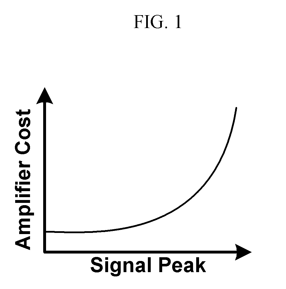
Package cost generally dominates for low peak-power amplifiers.
However, beyond some point, additional peak-power capability results in exponentially-increasing amplifier costs.
The complexity and cost of an amplifier is highly dependent on the maximum instantaneous power it must accommodate.
In wireless communications and networking, however, clipping is unacceptable.
Because spectral regrowth adds unacceptable frequency components to the signal, spectrum regulations do not permit clipping as a solution for high-power amplifier requirements.
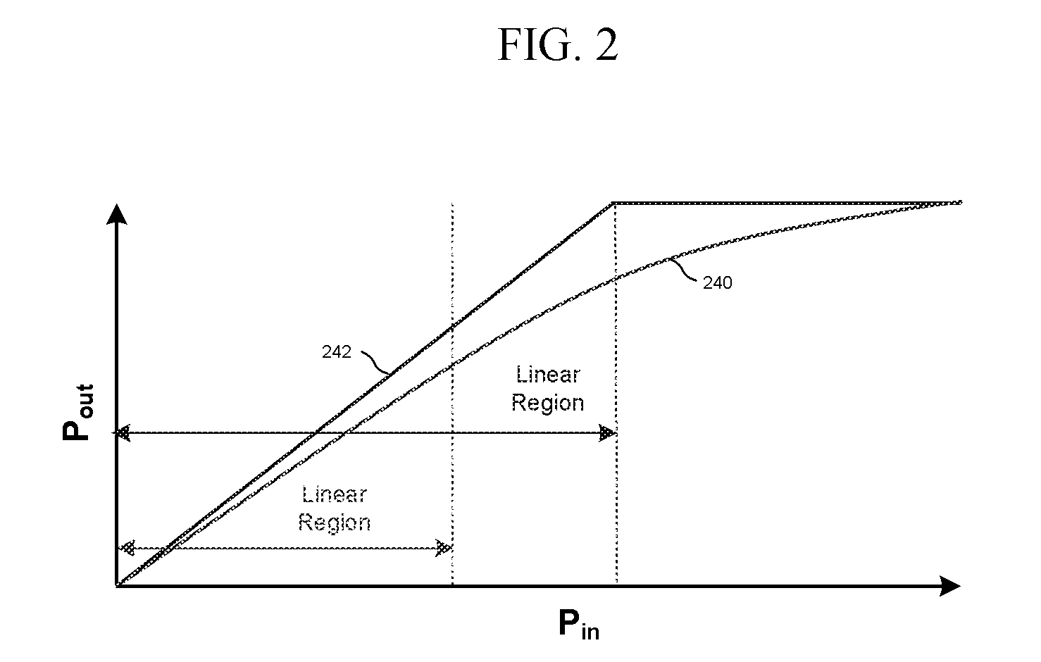
However, at higher input signal power levels, the amplifier output reaches an upper limit, the amplifier saturation power, which cannot be exceeded.
Operation of the amplifier near its nonlinear amplification region generates unacceptable nonlinear noise which violates regulatory spectral masks, forcing operation at a lower input power level.
However, since a four-signal high-power diplexer can cost on the order of $10,000, an alternative solution in the form of MCS was developed.
Thus, MCS remains an incomplete solution to the diplexer problem of earlier transmission systems until peak reduction in MCS is effectively addressed.
While this technique reduces the peaks, it also significantly degrades the performance of error-correction coding, and has thus failed to find any significant market acceptance.
While these approaches offer improvement, and at least two patents (U.S. Pat. Nos. 6,366,319 and 6,104,761) have been granted for such an approach, they both add excessive noise to the signal.
These approaches also do not offer a comprehensive and systematic peak-reduction processing solution when the MCS channels are dynamically varying in relative power levels and when the EVM requirements of each channel also dynamically vary, as is the case with real-world MCS transmission.
However, hard-limiting in this manner introduces passband nonlinear interference which cannot be removed by out-of-band filtering, and even out-of-band DFT filtering distorts the signal.
However, the prior art failed to recognize several critical factors involved in achieving optimal peak reduction.
The prior art described only static frequency-dependent attenuation of the out-of-band excursion spectral components, and pointedly instructed to “distort the in-band (i.e. passband) component of the difference (excursion) as little as possible.” However, the nonlinearity represented by excursion formation generates relatively uniform spectral nonlinearity noise across the signal bandwidth.
Finally, the prior art failed to grasp the critical importance of applying dynamic scaling to different portions of the excursion prior to filtering in order to achieve significantly enhanced peak-reduction.

Method used


Image

  • Method and apparatus for adaptively controlling signals
  • Method and apparatus for adaptively controlling signals
  • Method and apparatus for adaptively controlling signals

Examples


Embodiment Construction

[0060]The peak-reduction concepts of the present invention as discussed below are presented primarily in the context of MCS (typically four WCDMA channels), since it simplifies the discussion to treat a smaller number of signal channels. However, the peak-reduction processing concepts of the present invention are equally applicable to OFDM signals. Similarly, the discussion below is presented in the context of wireless communications systems. However, the peak-reduction processing concepts of the present invention are equally applicable to, for example, digital radio and television broadcast systems, including wired, terrestrial and satellite broadcast systems. The invention may, for example, provide benefits in the processing of any signal conveyed via variations in electromagnetic or acoustic fields. The inventive concepts may therefore be applied in optical data transmission and audio systems. The present invention thus includes within its scope the processing of signals, or appa...


PUM


Abstract

A signal processing system according to various aspects of the present invention includes an excursion signal generator, a scaling system and a filter system. The excursion signal generator identifies a peak portion of a signal that exceeds a threshold and generates a corresponding excursion signal. The scaling system applies a real scale factor to contiguous sets of excursion samples in order to optimize peak-reduction performance. The filter system filters the excursion signal to remove unwanted frequency components from the excursion signal. The filtered excursion signal may then be subtracted from a delayed version of the original signal to reduce the peak. The signal processing system may also control power consumption by adjusting the threshold. The signal processing system may additionally adjust the scale of the excursion signal and / or individual channel signals, such as to meet constraints on channel noise and output spectrum, or to optimize peak reduction. The magnitude threshold, excursion signal and / or individual channel signals may also be adaptively adjusted based on, for example, a channel signal quality such as a noise level specification.

Description

CROSS-REFERENCE TO RELATED APPLICATIONS[0001]This application is a divisional of co-pending application Ser. No. 11 / 417,477, filed Apr. 27, 2006 to which priority under 35 U.S.C. §120 is claimed, the entire contents of which are incorporated herein by reference.FIELD OF INVENTION[0002]This invention relates generally to signal transmission systems, including those associated with cellular infrastructure, where signal peaks may be advantageously reduced, and more particularly to a method and apparatus for reduction of peak power requirements by adaptively controlling signals.BACKGROUND OF THE INVENTION[0003]Wireless communication basestations, networks, and other systems use power amplifiers to transmit signals to cellular phones, handheld messaging devices, computers, personal electronic assistants, and other devices. A power amplifier increases the average power of the transmitted wireless signal sufficiently to maintain a reliable communication link at any required distance. This ...

Claims


Application Information

Patent Timeline
Patent Type & Authority Applications(United States)
IPC IPC(8): H04L27/28H03C1/62H04B17/40
CPCH03F1/0205H03F3/24H03F2200/165H04L27/2624H03G3/3042H03G3/3047H04B1/0475H03F2200/258
Inventor MCCALLISTER, RONALD D.BROMBAUGH, ERIC M.
Owner CRESTCOM INC
Learn More