Internal-combustion-engine ignition diagnosis apparatus and internal-combustion-engine control apparatus

a technology of ignition diagnosis and internal combustion engine, which is applied in the direction of machines/engines, spark plugs, instruments, etc., can solve the problems of no malfunction of this kind that can be detected by an existing misfire detection system, deterioration of exhaust gas, etc., and achieve the effect of accurately diagnosing the condition of spark discharg

Active Publication Date: 2009-04-16
MITSUBISHI ELECTRIC CORP
View PDF1 Cites 11 Cited by
  • Summary
  • Abstract
  • Description
  • Claims
  • Application Information

AI Technical Summary

Benefits of technology

[0010]The present invention has been implemented in order to solve the foregoing problems in the conventional apparatuses; the objective of the present invention is to provide an internal-combustion-engine ignition diagnosis apparatus that can accurately diagnose the condition of a spark discharge.

Problems solved by technology

In recent years, problems of environmental conservation and fuel depletion have been raised, and also in the automobile industry, solutions to these problems have become big issues.
However, in the case of a multi-point ignition system, because, even when part of the ignition systems fail, combustion can be continued in many cases, no malfunction of this kind can be detected by an existing misfire detection system.
Accordingly, because required ignition energy cannot be obtained, deterioration in an exhaust gas (an emission) due to deterioration in the combustion condition and deterioration in the gasoline mileage due to output decrease are caused, whereby a disadvantage occurs, despite the realization of environmental conservation.
For example, in a failure mode such as a short circuit across the secondary coil of the ignition coil or a short circuit between the electrodes of an ignition plug, no-spark operation cannot be detected; therefore, it has been a problem that deterioration in the gasoline mileage and deterioration in the emission caused in the foregoing failure mode cannot be recognized.

Method used


Image

  • Internal-combustion-engine ignition diagnosis apparatus and internal-combustion-engine control apparatus
  • Internal-combustion-engine ignition diagnosis apparatus and internal-combustion-engine control apparatus
  • Internal-combustion-engine ignition diagnosis apparatus and internal-combustion-engine control apparatus

Examples


embodiment 1

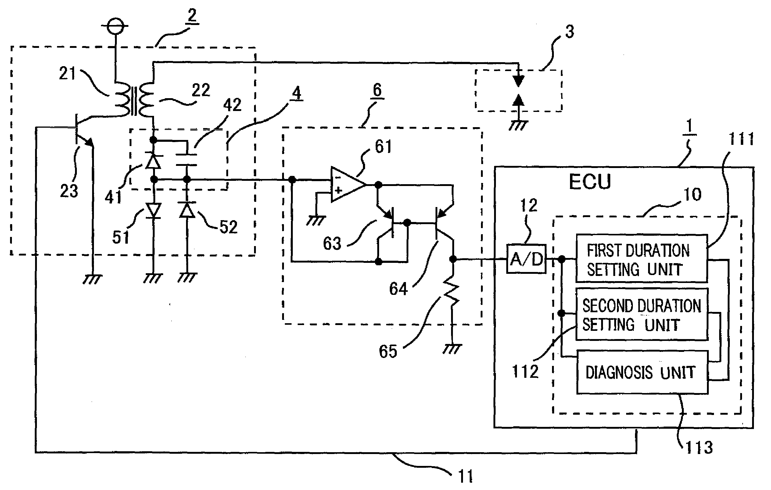
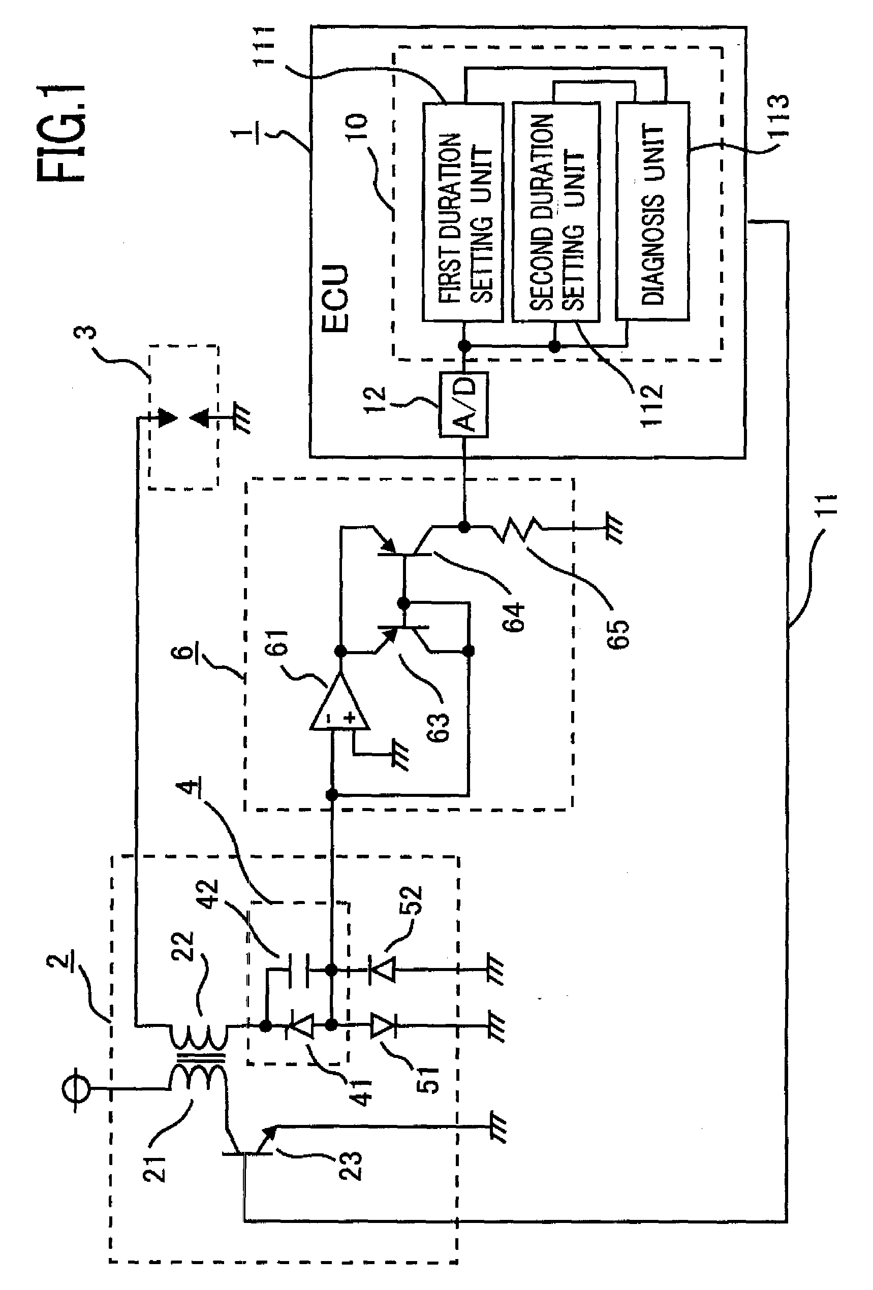
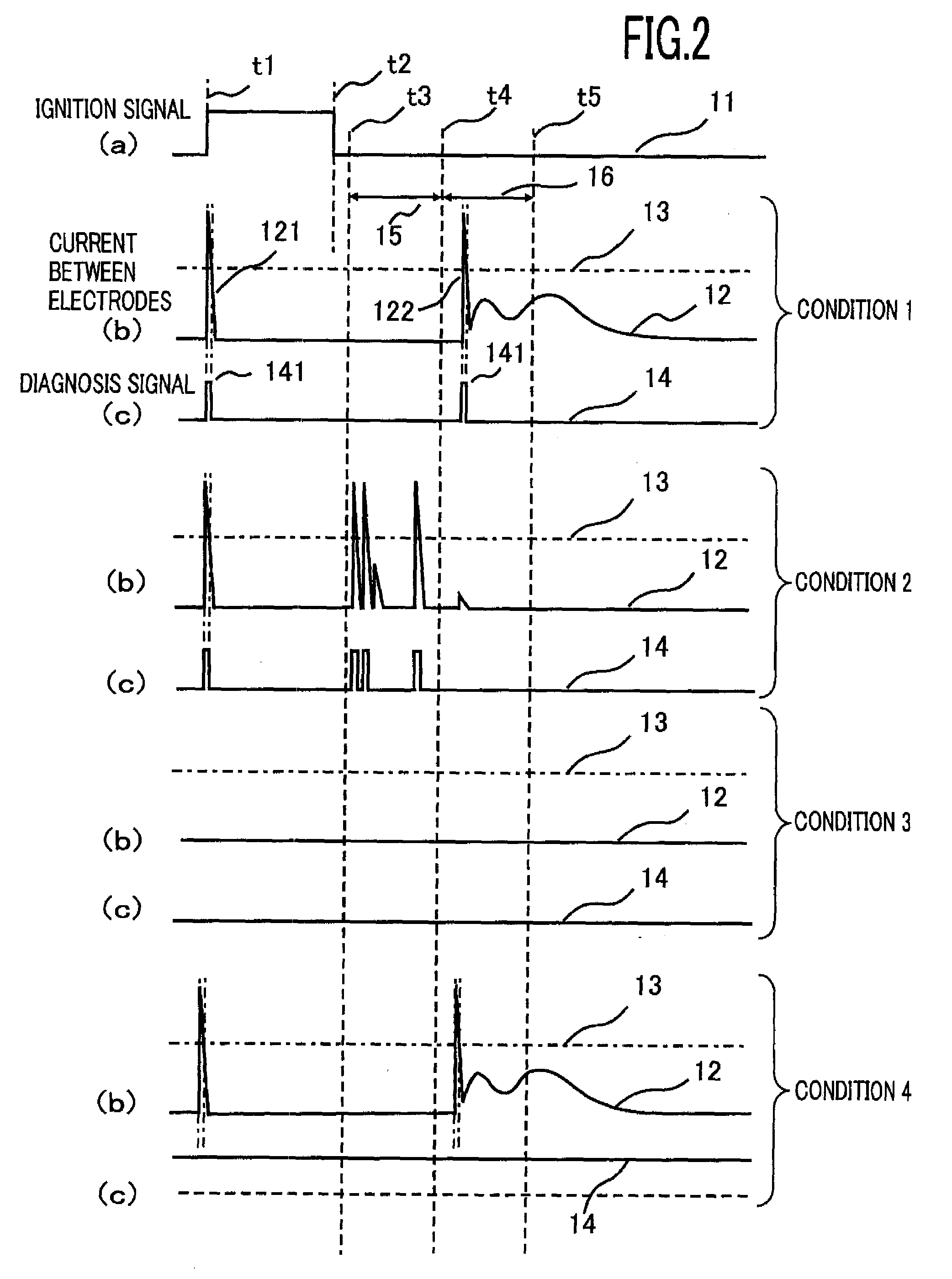
[0023]An internal-combustion-engine ignition diagnosis apparatus according to Embodiment 1 of the present invention will be explained below. FIG. 1 is a block diagram illustrating an internal-combustion-engine ignition diagnosis apparatus according to Embodiment 1 of the present invention; FIG. 2 is a timing chart for explaining the operation of internal-combustion-engine ignition diagnosis apparatus; FIGS. 3 and 4 are flowcharts for explaining the operation of internal-combustion-engine ignition diagnosis apparatus.

[0024]In FIG. 1, an engine control unit (referred to as “ECU”, hereinafter) 1 that controls an internal combustion engine (unillustrated) generates an ignition signal 11 for activating an ignition coil 2 as a high voltage device and inputs the ignition signal to the base of a switching element 23 connected in series to a primary coil 21 of the ignition coil 2. A secondary coil 22 of the ignition coil 2 is coupled with the primary coil 21 through a magnetic core; one term...

embodiment 2

[0063]Internal combustion engines in each of which a plurality of ignition devices is arranged in a single combustion chamber, i.e., in the same combustion chamber have been put to practical use. There exist a number of reasons why a plurality of ignition devices is provided in the same combustion chamber; firstly, in order to raise the combustion efficiency so as to enhance the thermal efficiency of the internal combustion engine; secondly, in order to apply an auxiliary measures to a case in which the combustibility is low.

[0064]In any of the foregoing cases, a plurality of ignition devices is utilized by necessity. Accordingly, when part of the plurality of ignition devices provided in the same combustion chamber fail, an expected effect of the internal combustion engine, such as an expected output, cannot be obtained; therefore, deterioration in the gasoline mileage and deterioration in the emission due to the spread of a noncombustible region are worried.

[0065]However, the fail...

examples of embodiment 2

Variant Examples of Embodiment 2

[0084]In addition, in the foregoing description, a case has been explained in which a biasing device included in an ignition diagnosis apparatus and a signal extraction device, which serves also as a comparison device, are arranged inside an ignition coil, and the ignition diagnosis apparatus is disposed inside an ECU; however, the configuration may be made in such a way that only the biasing device is disposed inside the ignition coil, and the signal extraction device and the ignition diagnosis apparatus are arranged inside the ECU.

[0085]Furthermore, the signal extraction device may be included, as either hardware or software, in the ECU.

[0086]By arranging a critical mass of devices in an ignition coil, the foregoing configuration can contribute to downsizing and weight saving of the ignition coil, and by forming the signal extraction device with software in an ECU, the number of components can also be reduced; therefore, the formation with software ...


PUM


Abstract

The internal-combustion-engine ignition diagnosis apparatus is configured in such a way that the first duration setting unit sets the first detection duration in a predetermined duration including a time instant when the spark discharge is generated, the second duration setting unit sets the second detection duration after the first detection duration, the diagnosis unit determines normality of the spark discharge, based on a signal state in the second detection duration, and regardless of the signal state in the second detection duration, determines abnormality of the spark discharge, based on a signal state in the first detection duration.

Description

BACKGROUND OF THE INVENTION[0001]1. Field of the Invention[0002]The present invention relates to an internal-combustion-engine ignition diagnosis apparatus that diagnoses the condition of a spark discharge generated by an ignition device and to an internal-combustion-engine control apparatus provided with the ignition diagnosis apparatus.[0003]2. Description of the Related Art[0004]In recent years, problems of environmental conservation and fuel depletion have been raised, and also in the automobile industry, solutions to these problems have become big issues.[0005]As solutions to the foregoing problems, many technologies that intend to raise the efficiency of an engine as much as possible have been developed; some of them utilize an exhaust gas recirculation method (referred to as “EGR”, hereinafter) in order to reduce an intake loss.[0006]In the EGR method, an exhaust gas, which is a burned material, is introduced again into a combustion chamber; in particular, because, in the cas...

Claims


Application Information

Patent Timeline
Patent Type & Authority Applications(United States)
IPC IPC(8): G01M15/04F02P3/01H01T13/58
CPCF02P15/02G01M15/11F02P17/12
Inventor TANAYA, KIMIHIKO
Owner MITSUBISHI ELECTRIC CORP
Why Eureka
Try Eureka