Panel with impact protection membrane

Inactive Publication Date: 2009-04-23
AIRBUS OPERATIONS LTD
View PDF21 Cites 8 Cited by
  • Summary
  • Abstract
  • Description
  • Claims
  • Application Information

AI Technical Summary

Benefits of technology

[0005]The leading edge panel can at least partially absorb the energy of an object such as a bird and thus protect structure (such as a front spar) behind the panel. The leading edge panel may be positioned in a variety of leading-edge locations on the aircraft, including but not limited to the leading-edge of a slat, wing, tail-plane, fuselage or engine nacelle.
[0

Problems solved by technology

Whilst being suitable for providing protection against a small projectile such as a bullet, the barrier is less effective against a larger projectile.
Also, the barrier is only effect

Method used


Image

  • Panel with impact protection membrane
  • Panel with impact protection membrane
  • Panel with impact protection membrane

Examples


Embodiment Construction

)

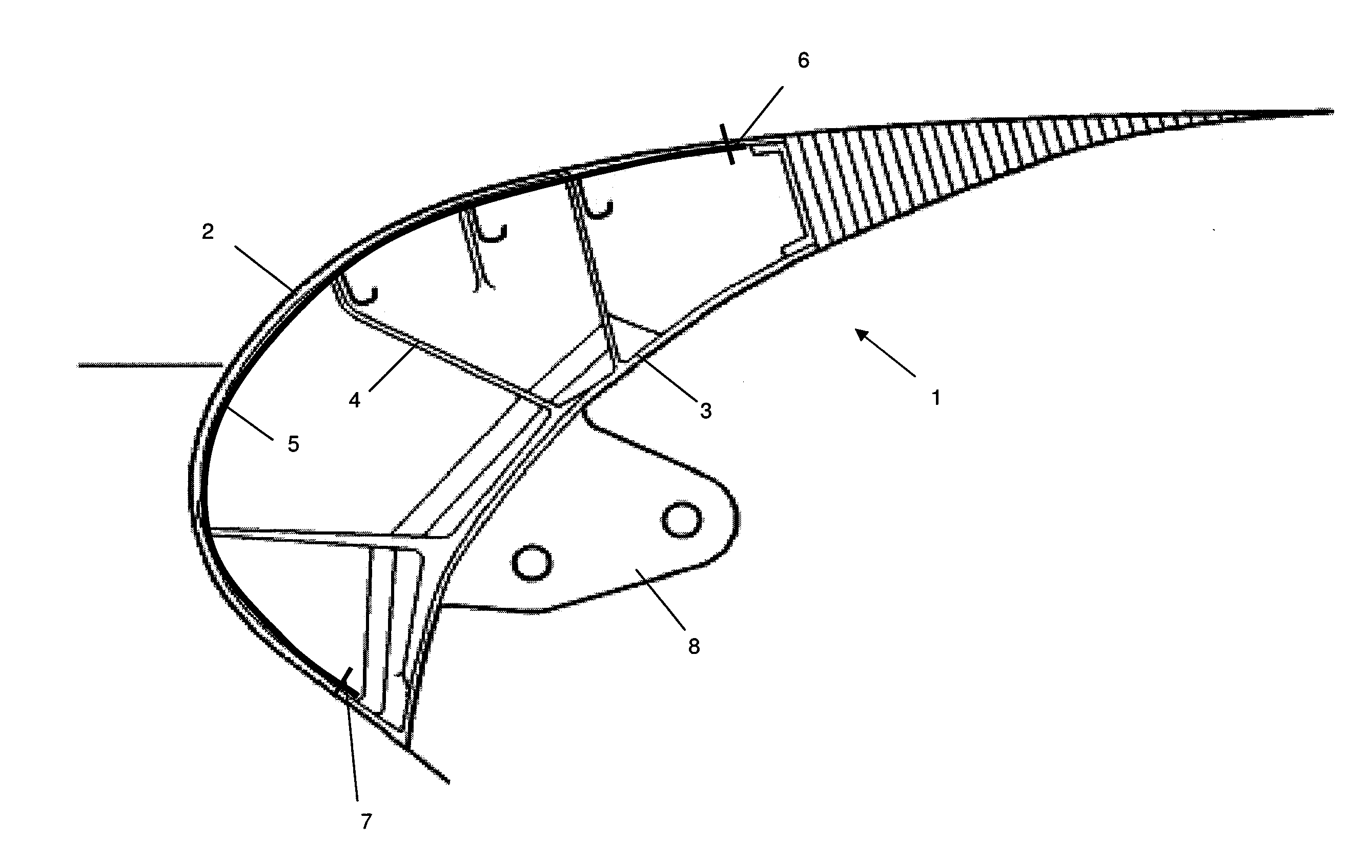
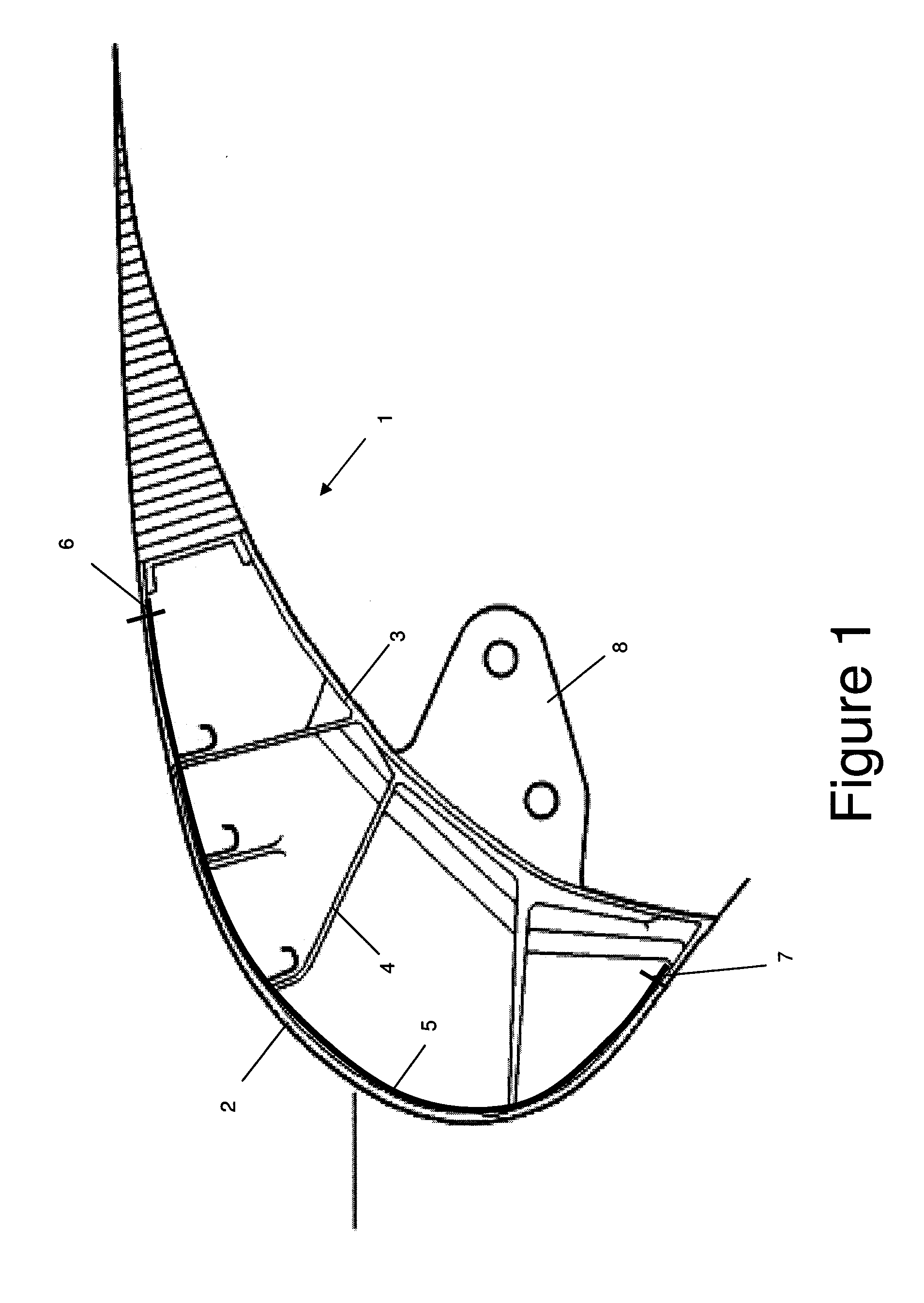
[0022]FIG. 1 is a cross-sectional view of a slat 1 which is attached to the leading edge of a wing (not shown) by a bracket 8. The slat 1 has a front skin panel 2 and a rear skin panel 3 which are connected by ribs 4.

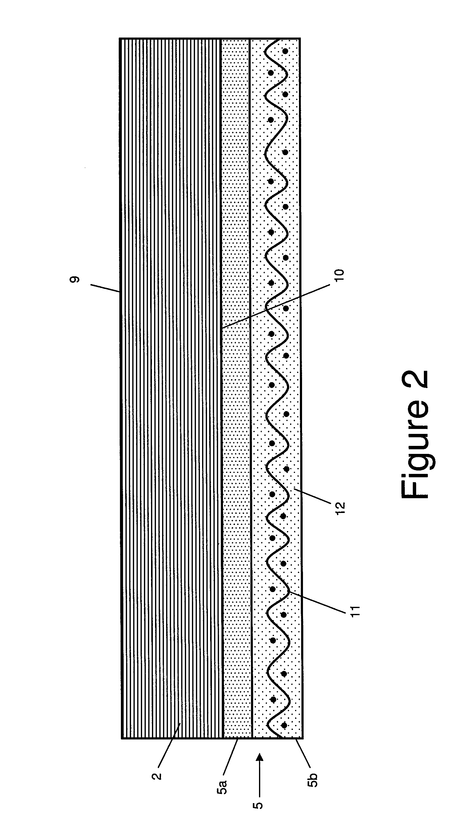
[0023]The front skin panel 2 presents the leading edge of the slat and is therefore susceptible to damage from bird strike. As shown in detail in FIG. 2, the skin panel 2 comprises an outer aerodynamic face 9; an inner face 10; and an impact protection membrane 5 bonded to the inner face 10.

[0024]The impact protection membrane 5 comprises an elastomeric layer 5b which is bonded to the inner surface 10 by an adhesion layer 5a . A method of co-curing the membrane 5 to the skin panel 2 is shown in FIG. 3. The skin panel 2 comprises a series of plies of pre-impregnated carbon-fibre reinforced epoxy resin. Each ply is conventionally known as a “prepreg”. The stack of prepregs is laid onto a female mould tool 20 in a partially cured state. The elastomeric layer 5b comprises ...


PUM

PropertyMeasurementUnit
Elastomericaaaaaaaaaa
Densityaaaaaaaaaa
Molecular weightaaaaaaaaaa

Abstract

An aircraft leading edge panel having an outer aerodynamic surface; and an inner surface carrying the elastomeric impact protection membrane. The membrane comprises a woven or knitted fabric which is impregnated with an elastomeric material. The membrane and the panel may be bonded by an adhesive or co-cured to bond the membrane to the panel. The membrane provides impact protection to the panel by de-bonding from the face of the panel and absorbing at least part of the energy of an object impacting the panel.

Description

FIELD OF THE INVENTION[0001]The present invention relates to an aircraft leading edge panel with an impact protection membrane, and a method of using a panel to providing impact protection.BACKGROUND OF THE INVENTION[0002]A projectile barrier and method is described in US 2007 / 0009694. An elastomeric bonding layer is spray-coated on the outside surface of a fuel tank. A composite expansion layer is then spray-coated on the bonding layer. Finally, a compression layer is spray-formed to the desired thickness on the outside of the expansion layer. When a bullet penetrates the fuel tank wall, the expansion layer comes into contact with the fuel and expands to fill the bullet hole. Whilst being suitable for providing protection against a small projectile such as a bullet, the barrier is less effective against a larger projectile. Also, the barrier is only effective in protecting a fuel tank wall. Also, the spray-coating process requires the elastomer to dissolve in a solvent, and so only...

Claims


Application Information

Patent Timeline
IPC IPC(8): B64C3/50B32B38/10
CPCB64C3/26B64C9/22B64C3/28
Inventor WEST, COLIN JOHNSUTTON, DAVID ALISTAIRBOOZARI, FARIBORZ F.
Owner AIRBUS OPERATIONS LTD
Why Eureka
Try Eureka