Dc-dc converter

a converter and dc-dc technology, applied in the direction of dc-dc conversion, power conversion systems, instruments, etc., can solve the problems of amplification compensation alone being insufficient to obtain adequate stability and response characteristics, and the power conversion efficiency of dc-dc converters is lowered

Inactive Publication Date: 2009-04-23
FUJI ELECTRIC SYST CO LTD
View PDF3 Cites 33 Cited by
  • Summary
  • Abstract
  • Description
  • Claims
  • Application Information

AI Technical Summary

Benefits of technology

[0013]The invention was devised in light of the above-described problems, and provides a DC-DC converter with a broad usage range as a DC power supply device, and in particular one which is capable of optimal phase compensation with a simple configuration, even when there are changes in the input voltage and load current.
[0016]Accordingly, by means of this invention, phase compensation circuit constants can easily be set, and moreover the output voltage can be set with stability over all regions even when the input voltage range and load current range are broad.

Problems solved by technology

If the capacitance value of the output capacitor is increased, the DC-DC converter is easily stabilized, but cost becomes a problem.
A method may also be used of providing a resistance circuit in series with the output capacitor to advance the phase, but this is not desirable due to the fact that the power conversion efficiency of the DC-DC converter is lowered.
However, in a DC power supply device for portable electronic equipment in which a rechargeable lithium battery or similar is used, the fluctuation ranges of the input voltage Vcc and load current Io of the DC-DC converter are set extremely broadly, and there are cases in which a simple combination of sensing compensation and error amplification compensation alone is insufficient to obtain adequate stability and response characteristics.

Method used


Image

  • Dc-dc converter
  • Dc-dc converter
  • Dc-dc converter

Examples


first embodiment

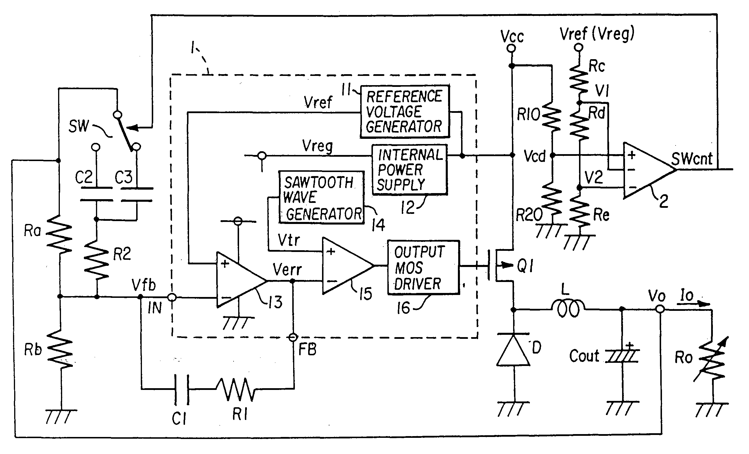
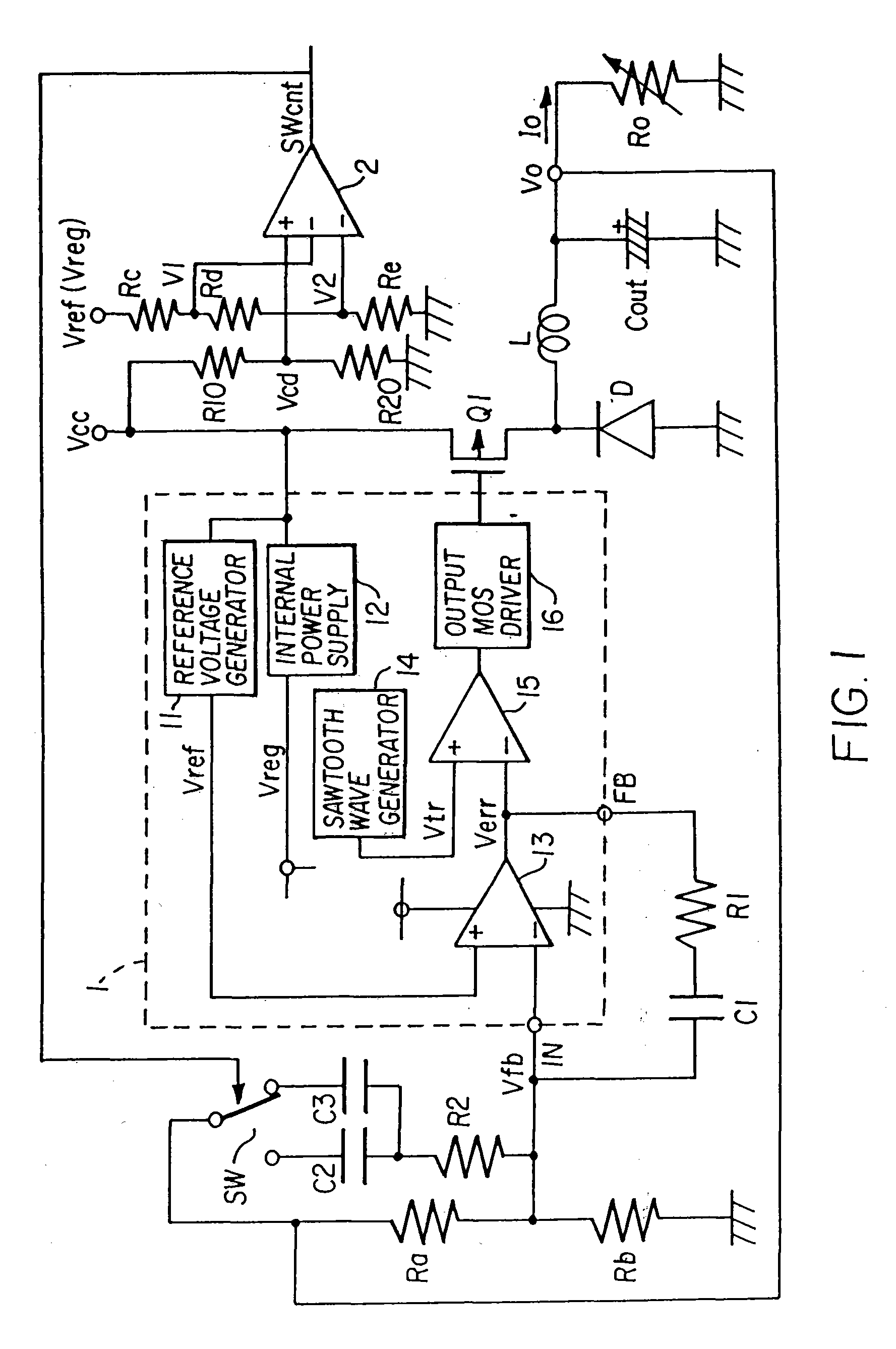
[0026]Below, preferred embodiments of the invention are explained referring to the drawings. FIG. 1 is a circuit diagram showing the DC-DC converter according to a Here, circuit elements corresponding to those of the circuit of the prior art in FIG. 8 are assigned the same symbols, and explanations thereof are omitted.

[0027]In this aspect, compared with the DC-DC converter of FIG. 8, a comparator 2 which outputs a switching control signal SWcnt, series resistors Rc, Rd, Re which set the reference voltages V1, V2 of this comparator 2, series resistors R10, R20 to voltage-divide the input voltage Vcc and generate a voltage signal Vcd which is supplied to the non-inverting input terminal of the comparator 2, a switch SW, and a capacitor C3 which is selected by the switch SW, are added. The comparator 2, series resistors Rc, Rd, Re, series resistors R10, R20, and switch SW forming switching control device. One end of the series resistors Rc, Rd, Re is connected to the constant voltage ...

second embodiment

[0036]FIG. 3 is a circuit diagram showing the DC-DC converter according to the invention. Here, a difference with the circuit of FIG. 1 is that a load current detection resistor Rs, one end of which is grounded, is added, connected in series to the load Ro, and the voltage thereon Vs is input to the non-inverting input terminal of the comparator 3. That is, whereas the switching control device of FIG. 1 is configured to perform switching according to the magnitude of the input voltage Vcc to the comparator 2, as the switching control device of FIG. 3, the comparator 3 performs switching according to the magnitude of the load current Io. The comparator 3, series resistors Rf, Rg, Rh, and reference voltages V3 and V4 are equivalent to the comparator 2, series resistors Rc, Rd, Re, and reference voltages V1 and V2 of FIG. 1, respectively, and perform the same respective functions. Also, explanations of cases in which hysteresis is and is not present are also similar, and so are omitted...


PUM


Abstract

A DC-DC converter, which controls the output voltage supplied to a load at a desired magnitude by performing on / off control of the input voltage using a switch, includes: an error amplifier for outputting the difference voltage between the output voltage and a preset reference voltage; and a plurality of phase compensation circuits for compensating the phase of the output voltage fed back to the error amplifier with different characteristics, whereby the DC-DC converter is configured such that changes in either the input voltage or in the load current flowing into the load are detected, and switching between the plurality of phase compensation circuits is performed. The frequency characteristic of each of the phase compensation circuits is determined for each of a plurality of demarcated fluctuation ranges of the input voltage or the load current.

Description

BACKGROUND OF THE INVENTION[0001]The invention relates to a DC-DC converter which changes a load current supplied to a load circuit by performing on / off control of a DC input voltage using a switching device to control a DC output voltage at a desired magnitude, and in particular relates to a DC-DC converter suitable for use as a DC power supply apparatus for portable electronic equipment using a rechargeable battery as a driving power supply.[0002]In portable telephones and other electronic equipment of the prior art, rechargeable lithium batteries and similar rechargeable batteries are installed as power sources. In general, the output voltage of a battery declines depending on circumstances of equipment usage, battery discharge, etc., and so a DC-DC converter is provided to convert direct current into direct current at an arbitrary voltage (DC-DC conversion) in order to convert the battery voltage into a constant voltage for output. However, even when using the same DC-DC convert...

Claims


Application Information

Patent Timeline
Patent Type & Authority Applications(United States)
IPC IPC(8): G05F1/00
CPCH02M3/156
Inventor NONAKA, TOMOMI
Owner FUJI ELECTRIC SYST CO LTD
Why Eureka
Try Eureka