Pulsed Dynamic Logic Environment Metric Measurement Circuit

a dynamic logic and measurement circuit technology, applied in the direction of pulse technique, instrumentation, device coding details, etc., can solve the problems of significant changes in circuit performance, frequency measurement places limitations on the real-time availability of measurement data,

Inactive Publication Date: 2009-04-23
IBM CORP
View PDF4 Cites 5 Cited by
  • Summary
  • Abstract
  • Description
  • Claims
  • Application Information

AI Technical Summary

Problems solved by technology

Such variations can lead to substantial changes in circuit performance and may vary rapidly.
However, frequency measurement places a limitation on the real-time (cycle-by-cycle) availability of the measurement data, as the frequency must be measured long enough to attain a desired resolution, and a typical static inverter chain delay measurement must be decoded to determine the length of the delay.

Method used


Image

  • Pulsed Dynamic Logic Environment Metric Measurement Circuit
  • Pulsed Dynamic Logic Environment Metric Measurement Circuit
  • Pulsed Dynamic Logic Environment Metric Measurement Circuit

Examples


Embodiment Construction

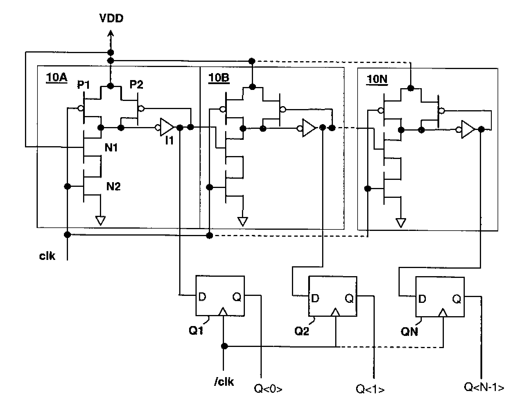
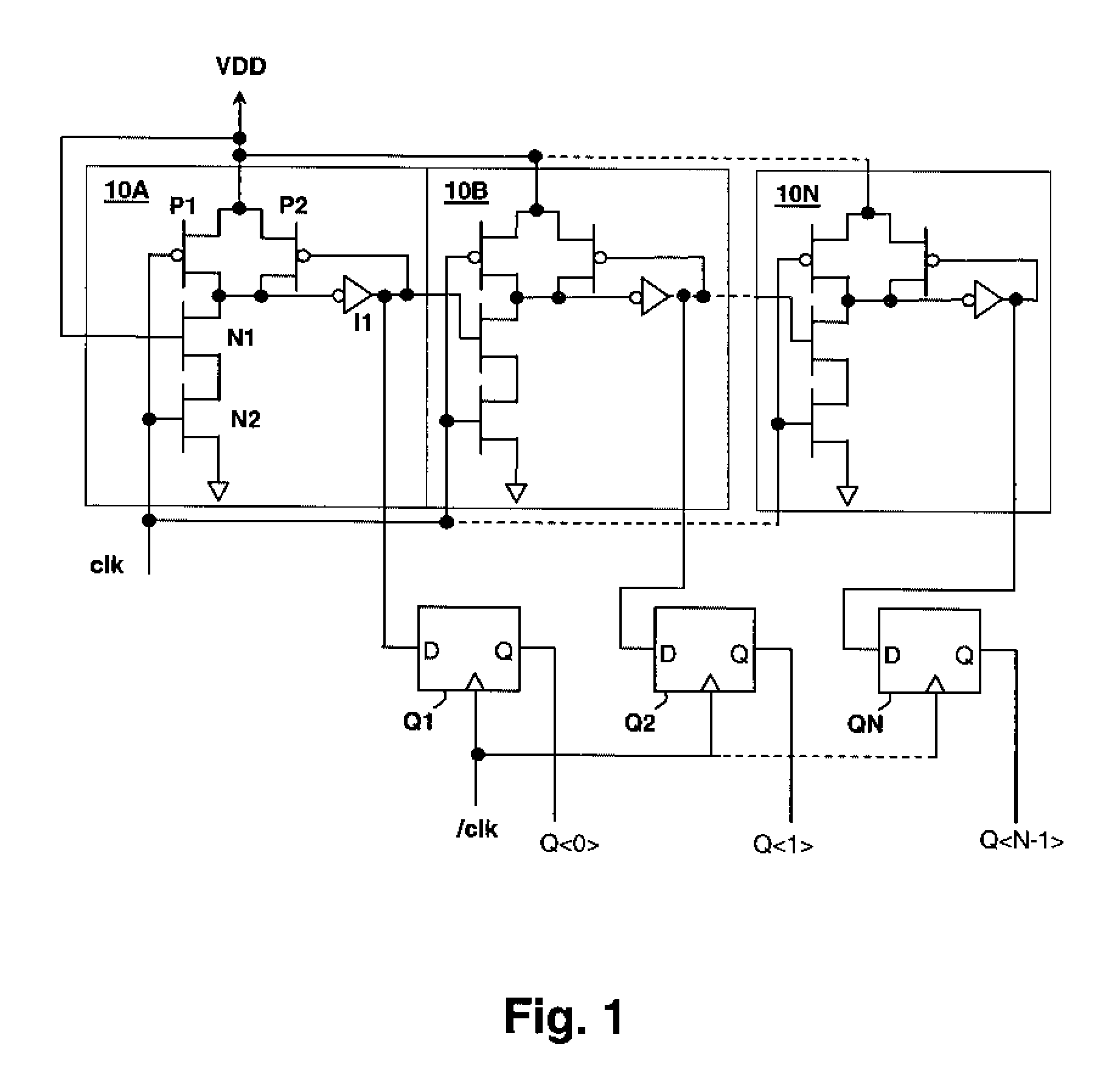
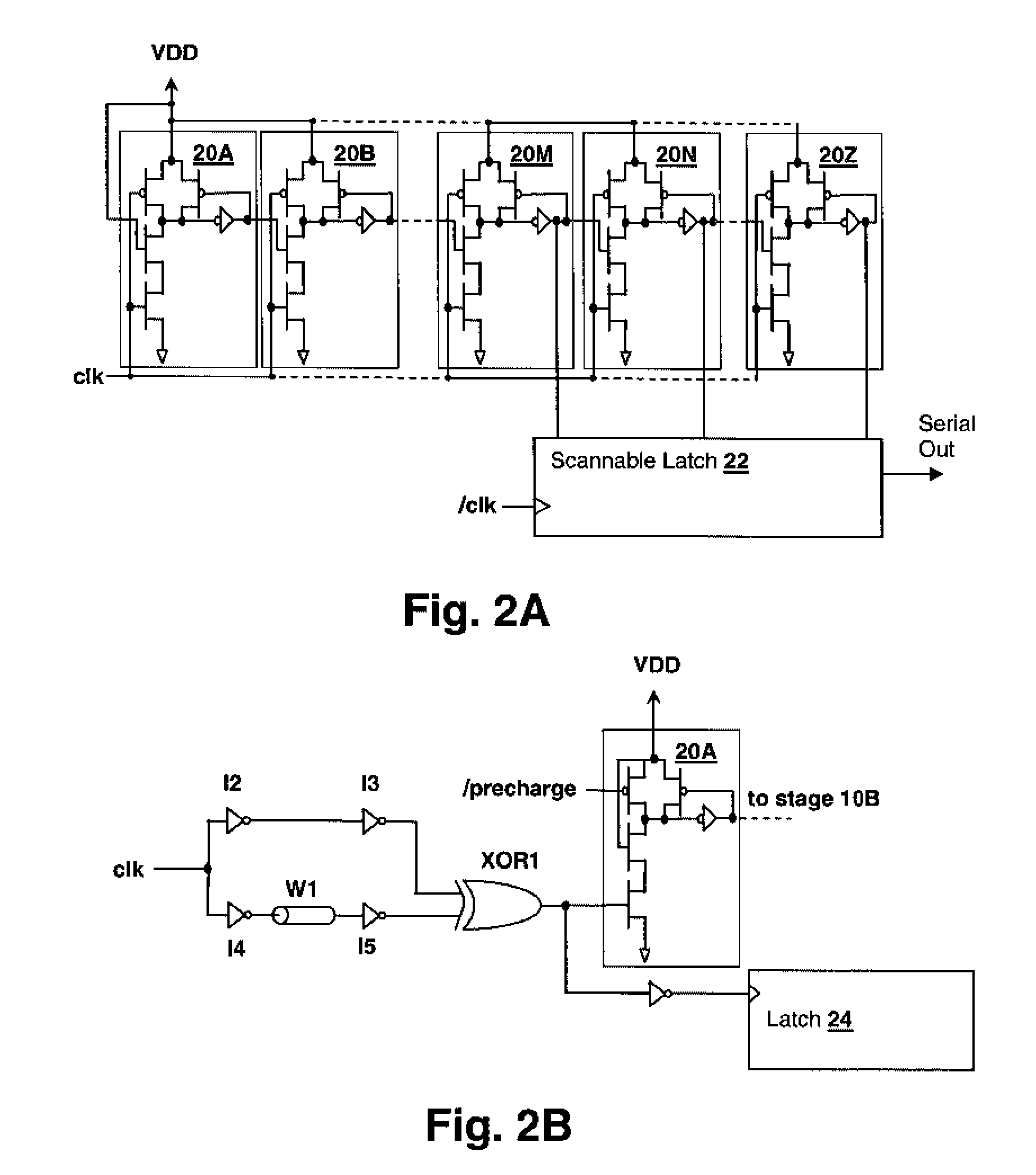
[0019]The present invention relates to circuits and methods for measuring circuit metrics such as supply voltage variation within an integrated circuit. The circuits are made very compact by the use of dynamic logic stages that evaluate in response to a pulse that is applied to the clock (evaluate input) to multiple cascaded dynamic logic stages that have a delay dependent upon the circuit metric, e.g., supply voltage, to be measured. A pulse generating circuit generates a pulse having a constant width. The last dynamic logic stage to evaluate (and the first dynamic logic state not to evaluate) thereby indicate the width of the pulse with respect to the delay of the dynamic logic stages. The input to the first dynamic logic stages is generally hard-wired to cause the dynamic logic stages to evaluate, and the last dynamic logic stage to evaluate (and the first dynamic logic state not to evaluate) thereby indicates the delay of the dynamic logic stages as the “evaluate” value proceeds...


PUM


Abstract

A pulsed dynamic logic environment metric measurement circuit provides self-referenced, low area / cost and low power measurement of circuit environment metrics, such as supply voltage. A cascade of dynamic logic stages is clocked with a pulse having a width substantially independent of an environment metric to which the delay of the dynamic logic stages is sensitive. The number of dynamic logic stages that evaluate within a given pulse provides a direct measure of the pulse width, and thus the value of the circuit metric. The pulse may be generated from a logical exclusive-OR combination of a clock signal provided from two circuit paths that differ in sensitivity to the environment metric to be measured. One circuit path may have a delay substantially determined only by wire delay, which is not substantially sensitive to circuit environment metrics such as power supply voltage.

Description

BACKGROUND OF THE INVENTION[0001]1. Field of the Invention[0002]The present invention is related to measurement circuits for measuring metrics such as circuit environment variables, and more particularly to a dynamic logic metric measurement circuit.[0003]2. Description of Related Art[0004]Environmental measurement circuits are finding application in integrated circuits such as processor cores, in which it is useful to evaluate and / or monitor variation in circuit environment metrics such as temperature and supply voltage. Such variations can lead to substantial changes in circuit performance and may vary rapidly. Therefore, it is desirable to make real-time measurements without increasing power consumption significantly, and without requiring large circuit area.[0005]Existing delay-based measurement circuits typically employ a chain of static logic inverters in a delay line or ring-oscillator arrangement. The delay of the delay line is sensitive to one or more environment metrics an...

Claims


Application Information

Patent Timeline
Patent Type & Authority Applications(United States)
IPC IPC(8): H03K19/00
CPCG01R31/2884H03M11/02G06F11/24
Inventor AGARWAL, KANAK B.
Owner IBM CORP
Why Eureka
Try Eureka