Puncture Device

a technology of puncture device and needle point, which is applied in the direction of catheters, trocars, infusion needles, etc., can solve the problems of reducing the strength of the puncture, deteriorating the puncture performance, and the inability of the needlepoint to reach a targeted blood vessel, and achieves small puncture resistance.

Active Publication Date: 2009-04-23
TERUMO KK
View PDF4 Cites 24 Cited by
  • Summary
  • Abstract
  • Description
  • Claims
  • Application Information

AI Technical Summary

Benefits of technology

[0026]According to the invention, since an outer needle does not collapse or rise at the time of puncture and has small puncture resistance, each of an operator and a patient has a light load.

Problems solved by technology

However, if a needle tube is made thin, its strength is reduced to become yielding, deteriorating puncture performance (accessibility of a needlepoint to a target site of a living body).
In other words, the resistance of skin, subcutaneous fat, muscle tissue or the like deforms the needle tube, which makes it impossible for the needlepoint to reach a targeted blood vessel.
In particular, if a puncture is made to an artery located deep in the living body, such a defect appears dominantly and high frequently.
This may make it probable not to accurately and quickly recognize catch of the blood vessel.
However, the late flashback has a bad influence on the operation of advancing the inner and outer needles in a delicate distance.
For instance, the inner needle may be inserted too deep so that it injures the opposite side of the blood vessel or impales the blood vessel.

Method used


Image

  • Puncture Device
  • Puncture Device
  • Puncture Device

Examples


examples

[0109]A description is next made of a specific example of the puncture device of the present invention.

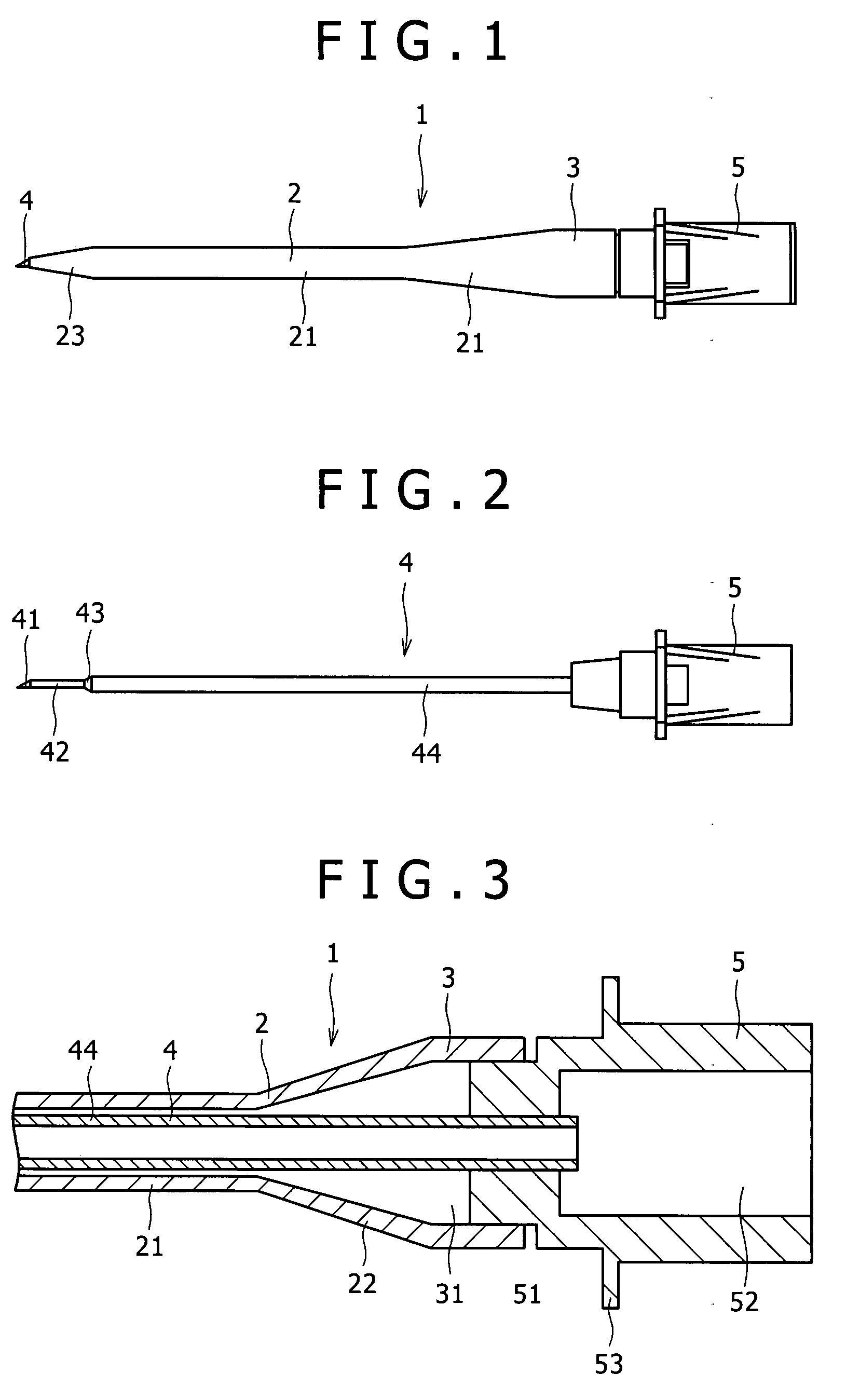
[0110]The puncture device shown in FIGS. 1 to 4 was manufactured. The dimensions of the puncture device are as follows:

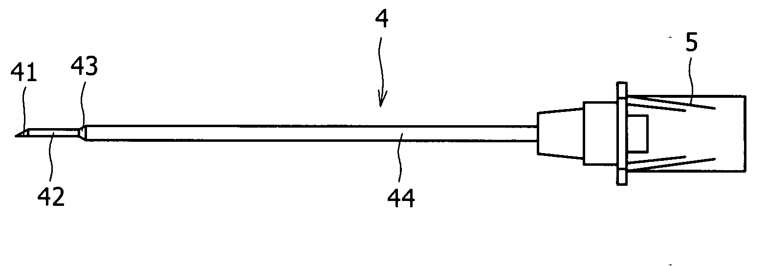
[0111]The outer diameter of the small diameter portion 42 of the inner needle 4: 0.90 mm

[0112]The length of the small diameter portion 42 of the inner needle 4: 6 mm

[0113]The length of the intermediate portion 43 of the inner needle 4: 3 mm

[0114]The outer diameter of the large diameter portion 44 of the inner needle 4: 1.25 mm

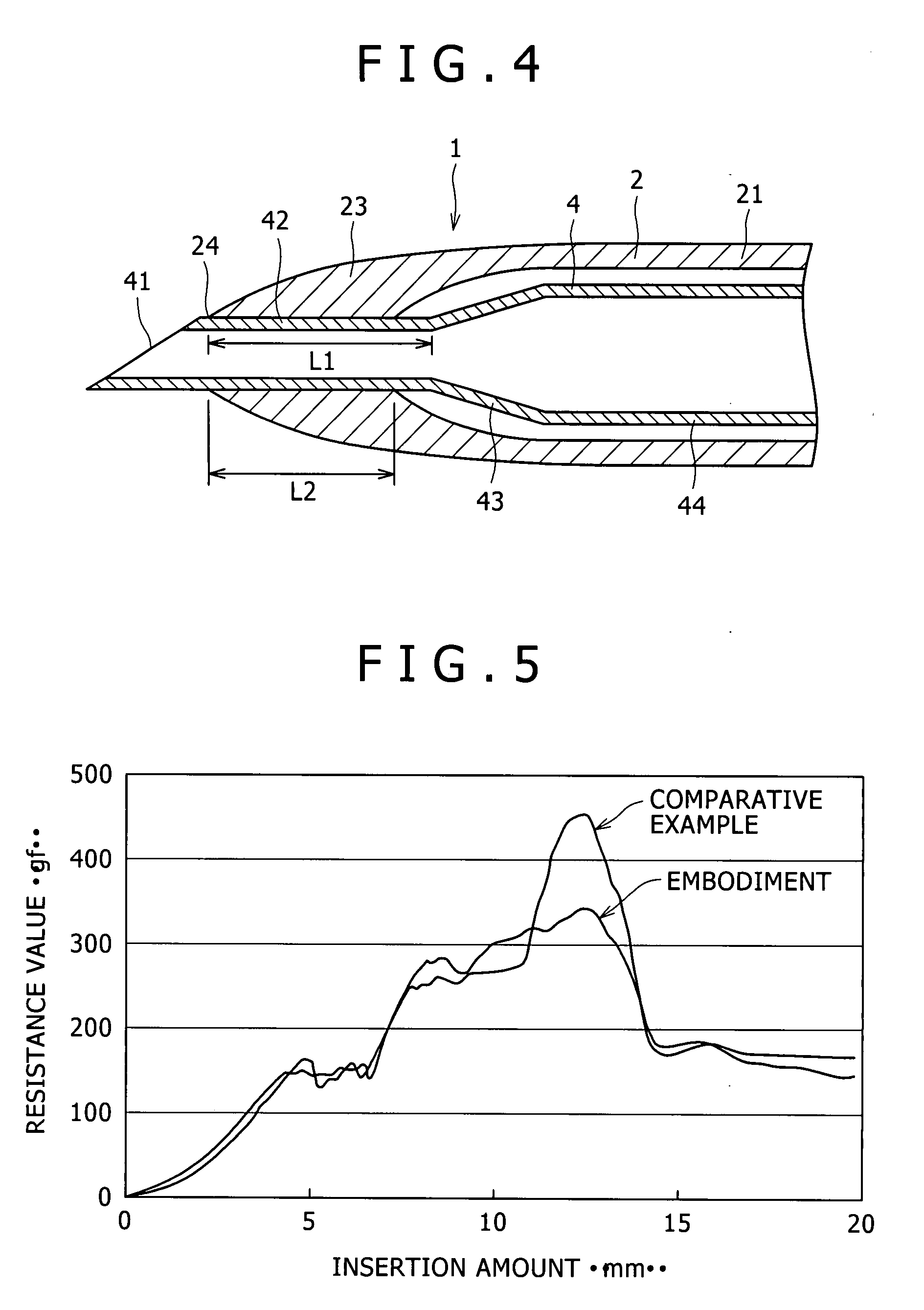
[0115]The length (L2) of a portion of the outer needle 2 in close contact with the small diameter portion 44 of the inner needle 4: 5 mm

[0116]The inner diameter of the outer needle 2 at a portion corresponding to the boundary portion between the small diameter portion 42 and intermediate portion 43 of the inner needle 4: 0.98 mm

[0117]The inner diameter of the outer needle 2 at a portion corresponding to the large diameter portion of the inner ...


PUM


Abstract

A puncture device is provided that does not allow an outer needle to collapse or rise at the time of puncture and exhibits small puncture resistance.
A puncture device 1 includes: a hollow outer needle 2; an outer needle hub 3 provided at a proximal end portion of the outer needle 2; a hollow inner needle 4 inserted into the outer needle 2 for use; and an inner needle hub 5 provided at a proximal end portion of the inner needle 4. The inner needle 4 includes, from the distal side, a sharp needlepoint 41, a small diameter portion 42 having an almost uniform outer diameter; an intermediate portion 43 formed as a tapered portion which is progressively increased in outer diameter as it goes toward the proximal end; and a larger diameter portion 44 having inner and outer diameters larger than inner and outer diameters, respectively, of the small diameter portion 42. If the puncture device 1 is assembled, the needlepoint 41 is most projected from the distal opening 24 of the outer needle 2 and the proximal end of the small diameter portion 42 and the distal end of the large diameter portion 4 are located inside the outer needle 2. The inner diameter of the outer needle 2 at a portion L1 where the outer needle 2 covers the small diameter portion 42 of the inner needle 4 is smaller than the large diameter portion 44 of the inner needle 4.

Description

TECHNICAL FIELD[0001]The present invention relates to a puncture device.BACKGROUND ART[0002]A treatment of inserting a catheter such as a balloon catheter and a guiding catheter or a lead wire of a cardiac pacemaker into a blood vessel is performed by using an indwelling needle assembly (see e.g. Patent Document 1) and a sheath introducer. The indwelling needle assembly includes an outer needle and an inner needle inserted into the outer needle. The sheath introducer includes a sheath and a dilator inserted into the sheath.[0003]In general, an indwelling needle assembly in which an outer needle and an inner needle are assembled together (a needlepoint of the inner needle projects from the tip of the outer needle) is inserted into a blood vessel such as a femoral artery. The inner needle is next withdrawn from the outer needle to indwell only the outer needle. A guide wire is inserted into the inside of the blood vessel through the outer needle. A sheath introducer in which a sheath ...

Claims


Application Information

Patent Timeline
Patent Type & Authority Applications(United States)
IPC IPC(8): A61B17/34
CPCA61M5/158A61M2025/0687A61M25/0693A61M25/06
Inventor WADA, SATOSHISOMA, KATSUAKIYAGI, HIROSHI
Owner TERUMO KK
Why Eureka
Try Eureka