
Method for non-contact particle manipulation and control of particle spacing along an axis

Active Publication Date: 2009-04-30
TRIAD NAT SECURITY LLC
View PDF99 Cites 54 Cited by
  • Summary
  • Abstract
  • Description
  • Claims
  • Application Information

AI Technical Summary

Benefits of technology

[0009]At the same time, a transducer is used to create an axial acoustic standing wave field in the flow channel parallel to the axis of the flow channel. This drives the particles, which are already being focused to the center axis of the flow channel, to nodes or anti-nodes of the axial standing wave at half-wavelength intervals, depending on whether the particles are more or less dense and more or less compressible than the surrounding fluid. Once the particles have been focused and driven to half-wavelength positions along the center axis of the flow channel, the flow stream with particles spaced at definite intervals flows out of the flow channel. This allows for synchronization of droplet formation and particle arrival, such that a droplet is not created until a particle is present, or such that droplets always contain a particle. These droplets can then either be discarded or kept for further analysis.
[0010]Embodiments of the present invention may be combined with recent low cost flow cytometry developments in lasers (such as a self healing laser beam, a single laser focused to a line, multiple laser beams, and diode pumped solid-state lasers) and data acquisition systems (such as multianode photomultiplier tubes, fiber optics, avalanche photodiodes, low cost digital signal processing chips with onboard analogue-to-digital converters, and charge couple device technology), to create inexpensive low linear velocity parallel flow cytometry analyzers to maximize particle through-put. These embodiments of the present invention and assorted methods and devices can be combined with periodic droplet creation and new droplet-on-demand particle sorters (using focused piezo methods and flexural piezo methods) that are less limited by particle size to form less expensive large particle sorters.

Problems solved by technology

However, several factors limit the speed at which this process can take place.
The maximum drop formation rate requires nearly 3.45 MPa to drive 2.5×10⁵ drops per second, though practically, mechanical limitations of the flow cytometer as well as effects on cells restrict the pressure applied to the system, limiting the rate to 1.0×10⁵ drops per second.
Further, the uncertain position of the particles in the flow stream leads to empty droplets, droplets with multiple particles, and particles at the break-off point between one droplet and another, all of which can lead to aborted sorting events, and all of which greatly reduce the overall sort rate.
Particle sorters of this type have problems with large particles (particles of diameter greater than 1×10⁻⁴ meters) such as multicellular organisms, multicellular spheroids, and large microspheres typically used for combinatorial library synthesis.
However, these larger flow channels restricted the linear velocity of the flow stream due to problems caused by increased turbulence.
Combined, these factors restricted the sorting rate of large particles to roughly 1000 per second.
Some work has been done with acoustic focusing of particles, though this has not corrected the problem of random particle arrival.
Some alternative methods have been attempted, such as a high pressure air jet that deflects the flow stream unless an analysis indicates that the particles in the stream should be kept at which point the air jet shuts down allowing the particles to pass through (though this method is limited to only about 15-1000 particles per second), a fluidic switching approach which is typically mechanical in nature (limited to only about 500 particles per second), and a laser ablation approach (though this method is no faster than current techniques leaves significant cell debris and is not suitable for sorting of microspheres).

Method used


Image

  • Method for non-contact particle manipulation and control of particle spacing along an axis
  • Method for non-contact particle manipulation and control of particle spacing along an axis
  • Method for non-contact particle manipulation and control of particle spacing along an axis

Examples


Embodiment Construction

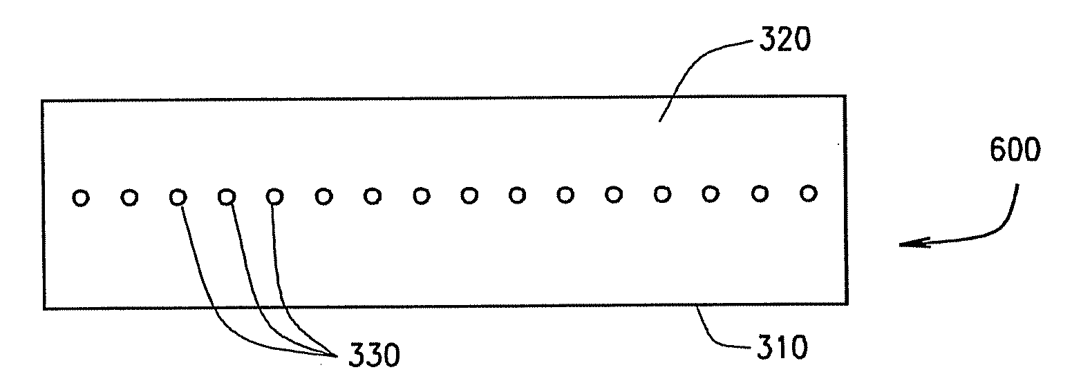
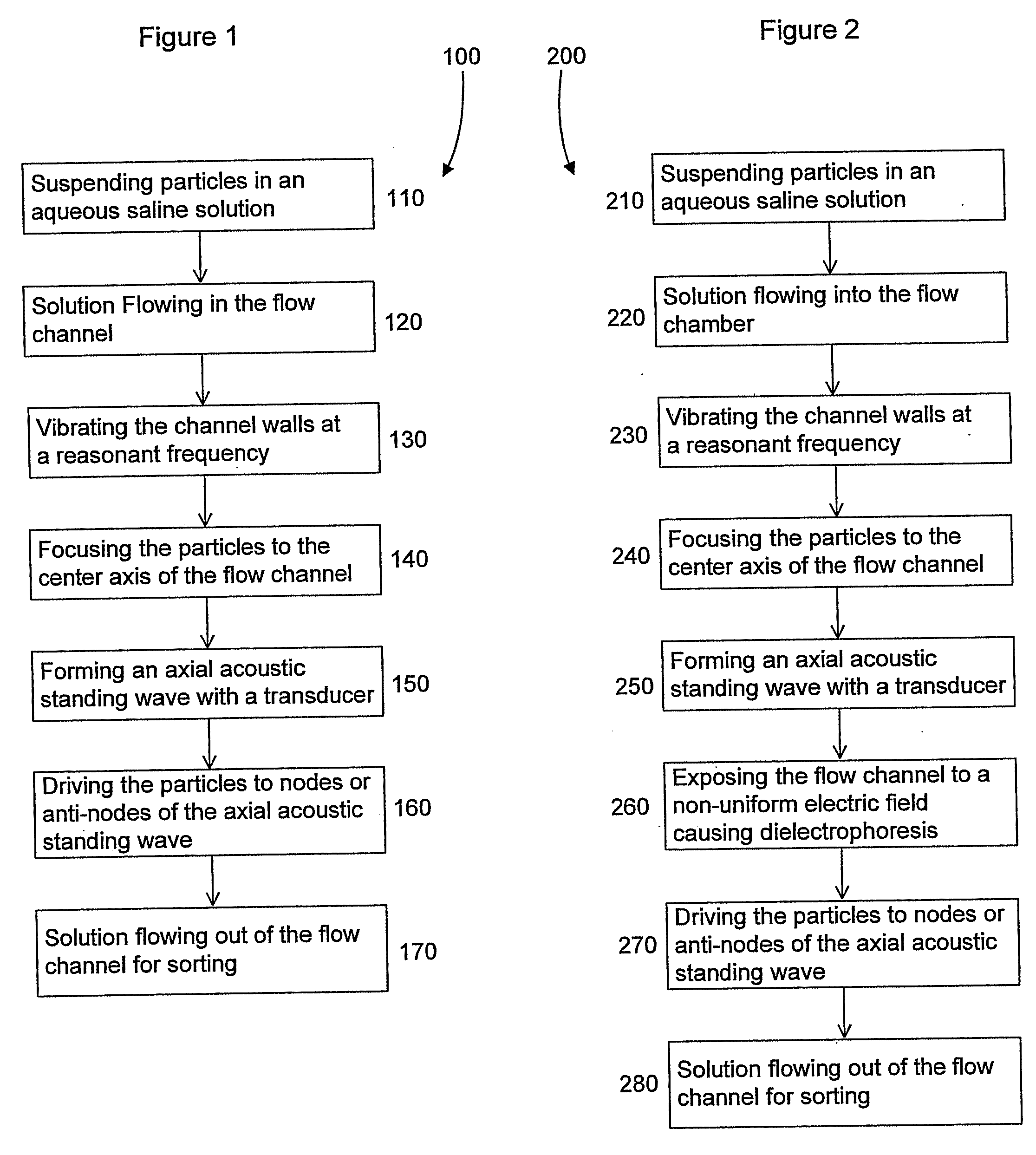
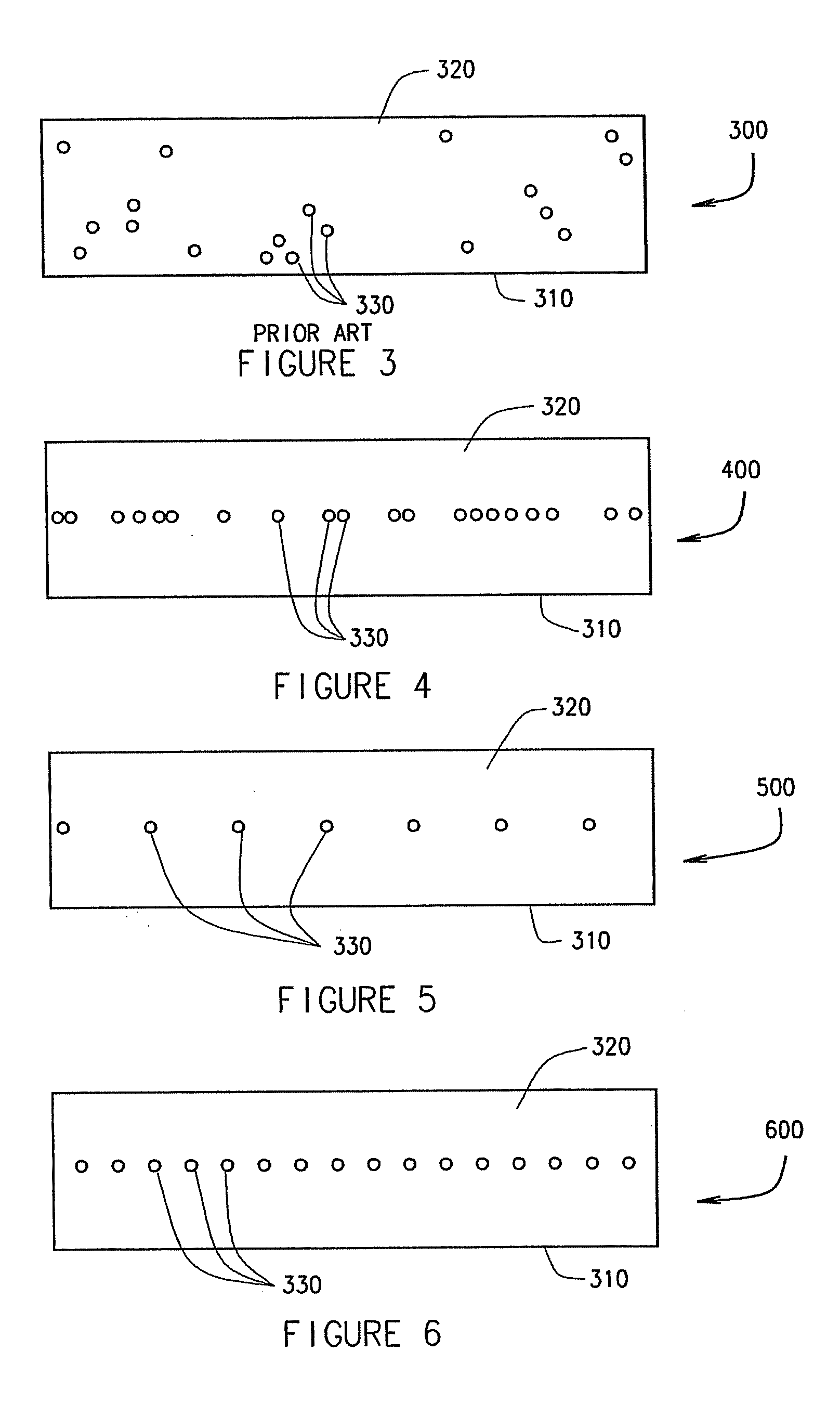
[0021]FIG. 1 illustrates a flow chart of a method for controllably spacing particles along an axis using acoustic standing wave fields 100 according to an embodiment of the present invention. The first step in the process of controlling the spacing between particles is suspending the particles in an aqueous saline solution 110. Next, the step of the solution flowing into the flow channel 120 occurs, where the step of vibrating the channel walls at a resonant frequency 130 takes place. The vibration of the chamber walls at a resonant frequency causes a radial acoustic standing wave field to form, which performs the next step of focusing the particles to the center axis of the flow channel 140. At the same time, the step of forming an axial acoustic standing wave with a transducer 150 occurs, where the axial acoustic standing wave is parallel to the center axis of the flow channel. This axial acoustic standing wave causes the step of driving the particles to nodes or anti-nodes of the...


PUM


Abstract

One or more of the embodiments of the present invention provide for a method of non-contact particle manipulation and control of particle spacing along an axis which includes axial and radial acoustic standing wave fields. Particles are suspended in an aqueous solution, and this solution then flows into the cylindrical flow channel. While the solution flows through the flow channel, the outer structure of the flow channel is vibrated at a resonant frequency, causing a radial acoustic standing wave field to form inside the flow channel in the solution. These radial acoustic standing waves focus the particles suspended in the solution to the center axis of the cylindrical flow channel.At the same time, a transducer is used to create an axial acoustic standing wave field in the flow channel parallel to the axis of the flow channel. This drives the particles, which are already being focused to the center axis of the flow channel, to nodes or anti-nodes of the axial standing wave at half-wavelength intervals, depending on whether the particles are more or less dense and more or less compressible than the surrounding fluid.

Description

STATEMENT REGARDING FEDERAL RIGHTS[0001]This invention was made with government support under Contract No. DE-AC52-06NA25396 awarded by the U.S. Department of Energy. The government has certain rights in the invention.BACKGROUND OF INVENTION[0002]The present invention relates to a method for controllably spacing particles along an axis. More specifically, the present invention relates to a method for manipulating particles and controlling their spacing along an axis without directly contacting the particles during droplet based flow cytometry.[0003]Piezoelectric droplet generation devices used for inkjets have been adapted for use with coulter volume and optical sensing to perform the first sorting of biological cells. The basics of this system have remained mostly unchanged since then. A hydrodynamically focused sample stream containing particles is optically interrogated (for scatter or fluorescence) either just prior or just after the focused stream is ejected into the air. The e...

Claims


Application Information

Patent Timeline
IPC IPC(8): G01H17/00
CPCG01N2015/142G01N15/1404
Inventor GODDARD, GREGORY RUSSKADUCHAK, GREGORYJETT, JAMES HUBERTGRAVES, STEVEN WAYDE
Owner TRIAD NAT SECURITY LLC
Features
  • Generate Ideas
  • Intellectual Property
  • Life Sciences
  • Materials
  • Tech Scout
  • Unparalleled Data Quality
  • Higher Quality Content
  • 60% Fewer Hallucinations
Learn More