
Method and apparatus for selective filtering of ions

a selective filtering and ion technology, applied in the field of methods and apparatus for selective filtering of ions, can solve the problems of space charge reducing the mass measurement accuracy of various instruments, changing the optimal excitation amplitude, and ion traps suffering from detrimental effects. the effect of lessening the detrimental effects

Active Publication Date: 2009-04-30
BATTELLE MEMORIAL INST
View PDF6 Cites 8 Cited by
  • Summary
  • Abstract
  • Description
  • Claims
  • Application Information

AI Technical Summary

Benefits of technology

The invention is a low m / z filtering apparatus and method that removes or reduces space charge effects in ion current. It uses a filtering plate or electrode positioned at the exit point of an ion funnel, which is biased and isolated from the funnel's voltages. The filtering electrode generates a barrier potential, which prevents ions with lower kinetic energy from exiting the funnel. This results in the filtering of lower m / z ions. The apparatus and method can be used in various devices and systems for gas-phase or solid-phase ion separation and analysis. It is particularly useful in biological or macromolecular ions and can be used in conjunction with other methods that reduce space charge effects.

Problems solved by technology

Further, space charge reduces the mass measurement accuracy in various instruments, including, e.g., Fourier transform ion cyclotron resonance (FTICR) MS.
Similarly, 3-D ion traps suffer from detrimental effects from excessive space charge which leads to shifts in secular frequencies, changes in optimal excitation amplitudes, and plasma effects.
Space charge can also cause radial stratification of ions and unwanted fragmentation in accumulation quadrupoles or multipoles in general.
However, data-dependent corrections and calibrations do not reduce or eliminate space-charge effects.
Further, such approaches are limited in that they cannot distinguish ions of interest from those that constitute background ions.

Method used


Image

  • Method and apparatus for selective filtering of ions
  • Method and apparatus for selective filtering of ions
  • Method and apparatus for selective filtering of ions

Examples


example 1

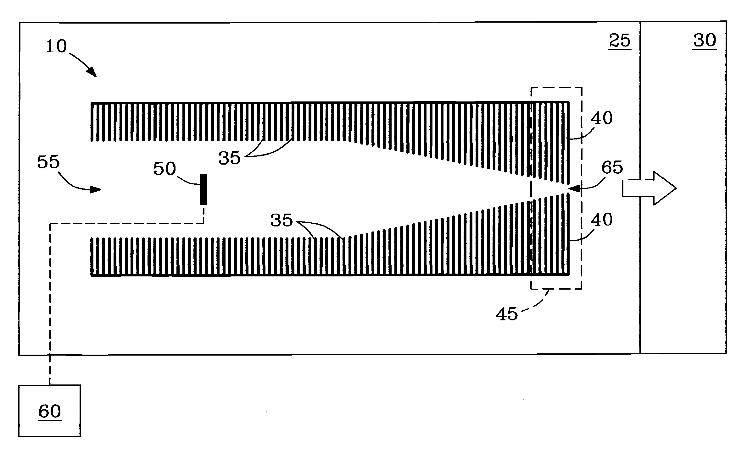
[0042]Example 1 describes tests showing ability of the conductance limiting electrode 40 of ion funnel 10 to perform selective low-mass filtering, e.g., as a low m / z filter 40.

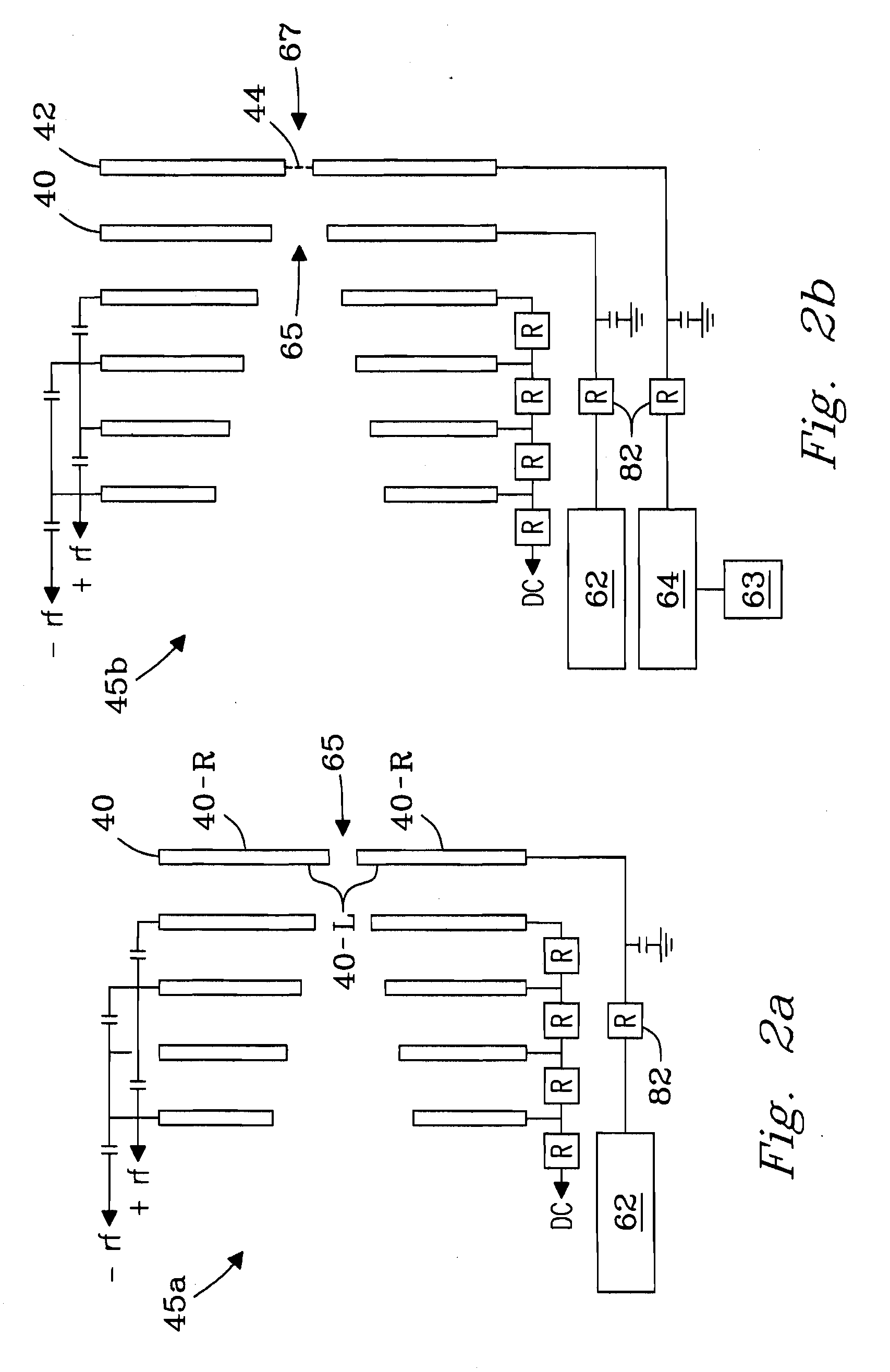
[0043]Ability of conductance limiting electrode 40 of ion funnel 10 to perform selective low-mass filtering was tested on a single quadrupole mass spectrometer (e.g., model 1100 quadrupole MS, Agilent, Palo Alto, Calif., USA) modified with an ESI / ion funnel source. The ESI / ion funnel configuration described in reference to FIG. 2b was employed. Ion funnel 10 was operated by applying an RF voltage of 500 kHz at 90 V peak-to-peak (90 Vp-p), but was not limited thereto. DC voltage applied to funnel plates 35 of ion funnel 10 yielded a constant gradient of 200 V at inlet 55 down to 5 V at exit aperture 65 of ion funnel 10. Pressure in funnel 10 was 1.9 Torr. ESI emitters were made by pulling sections of 100-μm i.d. / 200-μm o.d. fused silica capillary (Polymicro Technologies, Phoenix, Ariz., USA) either by hand with...

example 2

[0045]Example 2 describes tests relating m / z cut-off of filter plate 40 to the potential applied to filter plate 40 necessary to achieve filtering of low m / z ions.

[0046]A solvent mixture was prepared by combining methanol (Fisher Scientific, Pittsburgh, Pa., USA) and water (Nanopure Infinity Purification system, Barnstead, Dubuque, Iowa, USA) in a 50:50 ratio by volume and adding 1% by volume acetic acid (Sigma-Aldrich, St. Louis, Mo., USA). Filtering capacity of filter plate 40 was characterized by infusing and electrospraying (i.e., using an ESI / ion funnel source 25) the solvent mixture and acquiring mass spectra with the instrument described in Example 1. By observing the m / z cut-off at which chemical noise in the acquired mass spectra was eliminated, cut-off threshold could be ascertained as a function of voltage applied to filter plate 40. Filter plate 40 voltages were adjusted in one-volt increments in the range from about 12 V to about 18 V.

[0047]FIG. 4a presents a mass spect...

example 3

[0050]Example 3 describes the distribution of DC voltages and electric fields generated in the region near exit aperture 65 of filter plate 40 at an applied voltage of 15 V to filter plate 40. The DC electric field E was estimated using calculations based on the geometry shown in FIG. 1. As illustrated, e.g., in FIG. 2a, filter plate 40 can be considered a 3-dimensional plate having left and right surface planes (surfaces) 40-L and 40-R, respectively, and any suitable thickness (e.g., 0.5 mm), the left surface plane 40-L facing into the interior of ion funnel 10.

[0051]FIG. 5a shows the distribution of DC potentials observed for radial distances (r) of 0, 0.25, 0.5, 0.75 and 1 mm, respectively from the center of exit aperture 65 of filter plate 40 toward the radial edge of aperture 65 of filtering plate 40 as a function of axial coordinate “z” for rear section 45 of funnel 10. The origin of axial coordinate “z” is positioned at left-most surface plane 40-L (left surface) of filter pl...


PUM


Abstract

An adjustable, low mass-to-charge (m / z) filter is disclosed employing electrospray ionization to block ions associated with unwanted low m / z species from entering the mass spectrometer and contributing their space charge to down-stream ion accumulation steps. The low-mass filter is made by using an adjustable potential energy barrier from the conductance limiting terminal electrode of an electrodynamic ion funnel, which prohibits species with higher ion mobilities from being transmitted. The filter provides a linear voltage adjustment of low-mass filtering from m / z values from about 50 to about 500. Mass filtering above m / z 500 can also be performed; however, higher m / z species are attenuated. The mass filter was evaluated with a liquid chromatography-mass spectrometry analysis of an albumin tryptic digest and resulted in the ability to block low-mass, “background” ions which account for 40-70% of the total ion current from the ESI source during peak elution.

Description

[0001]This invention was made with Government support under Contract DE-AC05-76RLO1830 awarded by the U.S. Department of Energy. The Government has certain rights in the invention.FIELD OF THE INVENTION[0002]The present invention relates generally to a method and apparatus for selective filtering of ions. More particularly, the invention relates to a method and apparatus for selective filtering of low-m / z ions in conjunction with an electrodynamic ion funnel. The invention finds application in, e.g., analytical instruments and associated systems including, but not limited to, e.g., mass-selective instruments and components, coupled stages, and / or ionization sources and components including, but not limited to, e.g., MS, IMS / MS, FAIMS / MS, GC-MS, LC-MS, ESI-MS, and the like.BACKGROUND OF THE INVENTION[0003]Electrospray ionization (ESI) mass spectrometry (MS), or ESI-MS, has become a vital tool in biological research. Central to ESI-MS is the manipulation, transmission, and increasingl...

Claims


Application Information

Patent Timeline
Patent Type & Authority Applications(United States)
IPC IPC(8): B01D59/44
CPCH01J49/066G01N27/622G01N27/623
Inventor PAGE, JASON S.TANG, KEQISMITH, RICHARD D.
Owner BATTELLE MEMORIAL INST
Learn More