Methods and apparatuses for waveguiding luminescence generated in a scattering medium

a scattering medium and luminescence generation technology, applied in the field of optical waveguide technology, can solve the problems of not meeting the expected high efficiency of lc in practice, the cost of solar cells currently constitutes about 50% of the total system cost, and the concentrators employing geometric optic components work only under direct sunlight, so as to improve the performance of luminescent concentrators and reduce the loss of critical angle , the effect of increasing the output light intensity

Inactive Publication Date: 2009-04-30
E CUBE ENERGY TECH CO LTD
View PDF17 Cites 31 Cited by
  • Summary
  • Abstract
  • Description
  • Claims
  • Application Information

AI Technical Summary

Benefits of technology

[0010]Embodiments of present invention are directed to extracting and waveguiding luminescence generated in a medium so as to improve luminescent concentrator performance. By placing a high-efficiency transmission diffractive optic component and/or glass plate(s) on top of luminescent plates to redirect the re-emitted ...

Problems solved by technology

The cost of solar cells currently constitutes about 50% of the total system cost.
However, concentrators employing geometric optic components work only under direct sunlight and require tracking of the sun and excellent heat dissipation.
The expected high efficiency of LC in practice has not been reached for various reasons.
In the organic dye situation, because absorption and emission spectrum of a dye is very close to each other, and absorption spectrum does not cover enough useful solar spectrum, several dyes ...

Method used


Image

  • Methods and apparatuses for waveguiding luminescence generated in a scattering medium
  • Methods and apparatuses for waveguiding luminescence generated in a scattering medium
  • Methods and apparatuses for waveguiding luminescence generated in a scattering medium

Examples


Embodiment Construction

[0020]The foregoing background and summary, as well as the following detailed description of the drawings, will be better understood when read in conjunction with the appended drawings. For the purpose of illustrating the invention, there is shown in the drawings embodiments which are presently preferred. It should be understood, however, that the invention is not limited to the precise arrangements and instrumentalities shown. Throughout the drawings, like reference numerals refer to like elements. The terms “top” and “bottom” are used to distinguish between the different surfaces or covers. The use of the terms does not mean that the apparatus will always be oriented with the “top” surface or cover above the “bottom” surface or cover. Either position is considered to be within the scope of the invention.

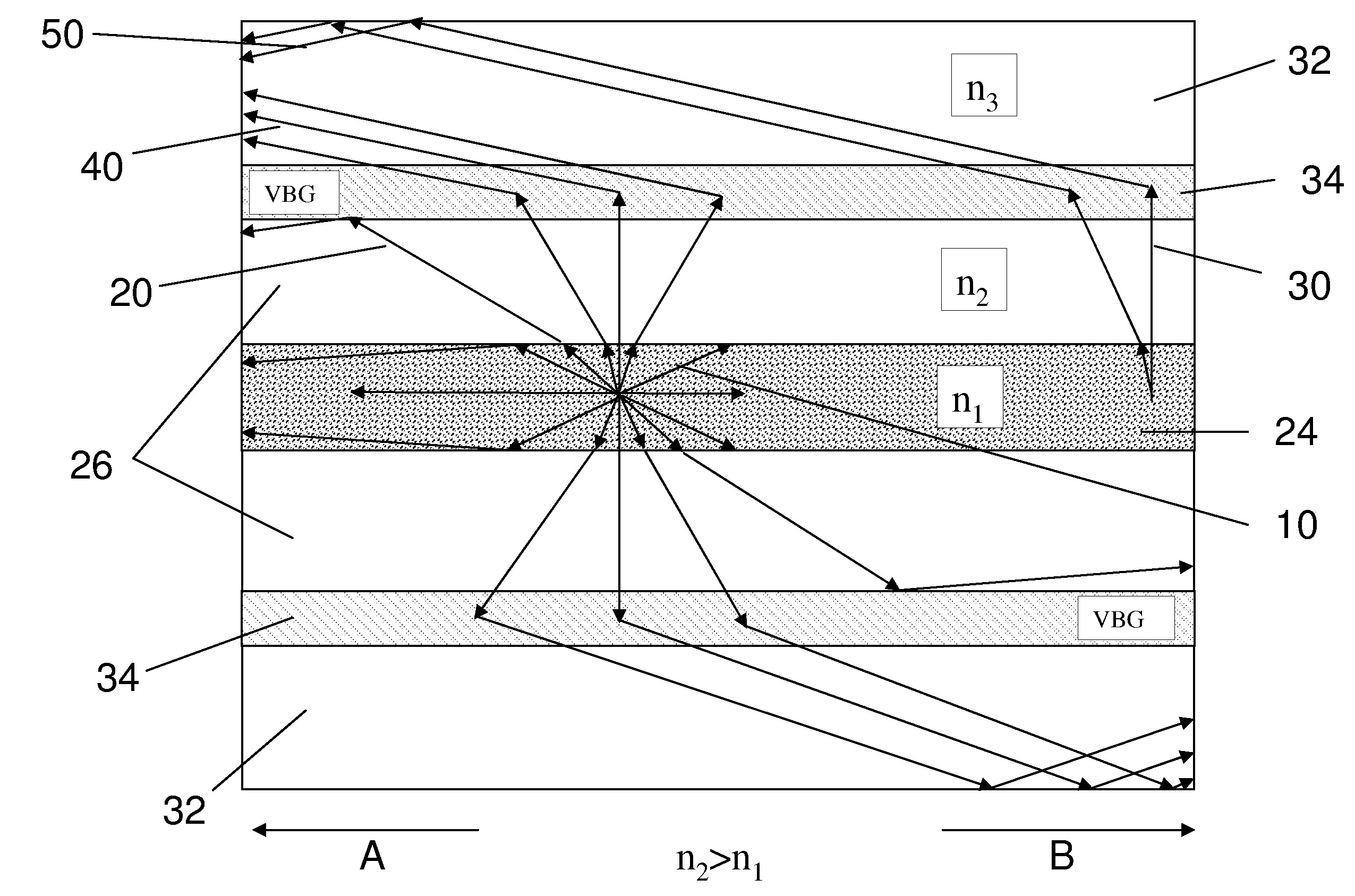
[0021]To overcome the above-mentioned deficiencies, an alternative luminescent plate designs are proposed in this invention. First, high efficiency inorganic luminescent materials ...


PUM


Abstract

The present invention is directed to a luminescent waveguide device, and methods of making thereof, that may be used to convert solar energy into electricity. In particular, the present invention relates to extracting and waveguiding luminescence generated in a scattering medium so as to improve luminescent concentrator performance. By stacking one or a pair of transparent plates of refractive index slightly smaller than that of luminescent plate but still larger than that of air, a much greater fraction of re-emitted light by the embedded luminescent particles can be extracted so that the detrimental effect of particle scattering can be minimized. Additionally, by additionally using a high-efficiency diffractive optic component in the structure to redirect the re-emitted photons with angles falling into the escape zone to much larger angles so these otherwise outgoing photons can be waveguided by total internal reflection. These improvements minimize the critical-angle loss and increase the output light intensity at the ends of the waveguide.

Description

[0001]This application claims the priority of U.S. Provisional Patent Application No. 60 / 934,872, filed Jun. 18, 2007.BACKGROUND OF THE INVENTION[0002]1. Field of the Invention[0003]Embodiments of the present invention are directed to the field of optical waveguide technology that optically confines photons of luminescence generated in a luminescent substrate and guides propagation of the light without significant optical loss. The present invention is directed to a luminescent waveguide device, and methods of making thereof, that may be used to convert solar energy into electricity.[0004]2. Description of the Related Art[0005]Solar cells are very important to the solar electric energy generation using PV technology in terms of conversion efficiency and cost-effectiveness. The cost of solar cells currently constitutes about 50% of the total system cost. Approaches to bring down the cost have been primarily focused on two fronts: the first is to reduce the cost of solar cells using n...

Claims


Application Information

Patent Timeline
IPC IPC(8): G02B6/10
CPCG02B6/10Y02E10/52H01L31/055
Inventor XIANG, XIAO-DONGSHAN, WEICHEN, ZITONG
Owner E CUBE ENERGY TECH CO LTD
Why Eureka
Try Eureka