Eureka AIR delivers breakthrough ideas for toughest innovation challenges, trusted by R&D personnel around the world.

Integrated Production of FCC-Produced C2 and Ethyl Benzene

a technology of ethyl benzene and c2 is applied in the field of hydrocarbon processing, which can solve the problems of high construction and maintenance costs, high energy consumption of such a splitter, so as to reduce the amount of recycle, reduce the cooling duty of the intercooler, and avoid the effect of cracking reaction

Active Publication Date: 2009-04-30
UOP LLC
View PDF6 Cites 15 Cited by
  • Summary
  • Abstract
  • Description
  • Claims
  • Application Information

AI Technical Summary

Benefits of technology

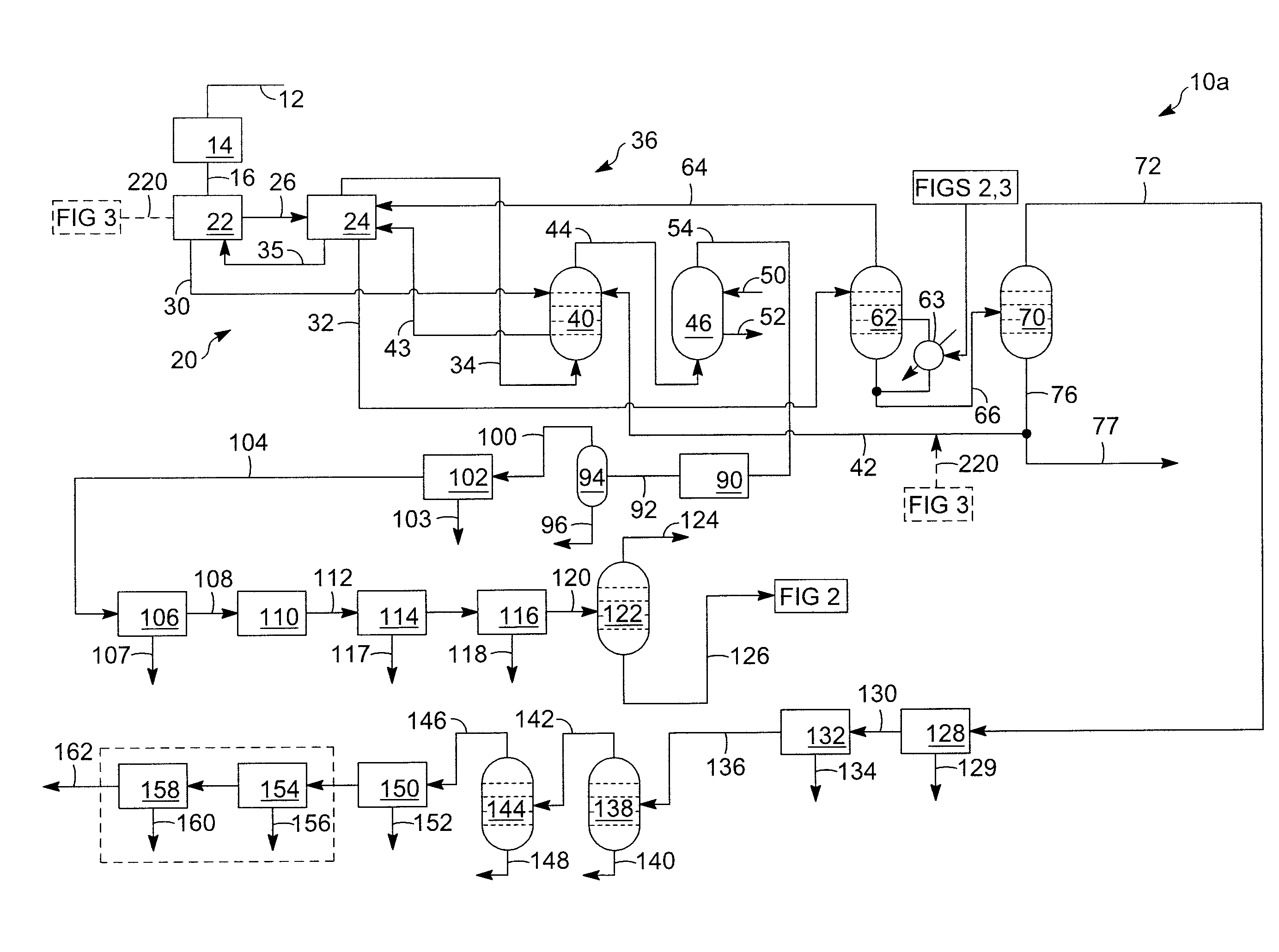
[0010]By linking the FCC process directly to the ethyl benzene alkylation process, substantial capital and energy costs savings are achieved. First, the need for an ethylene / ethane splitter column is eliminated as ethane is inert to the ethyl benzene alkylation process and does not hinder the process in an appreciable way. Second, along with the energy savings achieved by eliminating the ethylene / ethane splitter, additional energy savings are achieved by linking the intercoolers used to cool the alkylation reactor to one of the splitter columns of the FCC process. Further, additional savings may achieved by using the bottoms stream from the ethyl benzene column of the alkylation zone in one of two ways. First the EB column bottoms may be used as a solvent in the primary absorber of the absorption zone, thereby reducing the dependence upon debutanized gasoline recycle as a solvent for the primary absorber. Second, the EB column bottoms may be used as a co-feed with the effluent stream to the main column of the separation zone. Employing either of these strategies can reduce the debutanized gasoline recycle demand by 5 to 10%.
[0012]Further, the combined ethane / ethylene stream entering the alkylation reactor is cold as it preferably has just passed through a demethanizer. The combined ethane / ethylene stream has a temperature of less than 0° C. (32° F.) which further reduces the duty of the intercoolers used to cool the alkylation reactor.
[0014]As noted above, the hydrocarbon effluent generated in the FCC process passes through a separation zone to form a separator liquid stream and a separator vapor stream. C2− hydrocarbon materials are stripped from the separator liquid stream in a stripper column to form a C3+ hydrocarbon process stream substantially free of C2− hydrocarbons. This stripper column may be advantageously heated with heat generated in the alkylation reactor. Thus, heat may be transferred from the intercoolers used to cool the alkylation reactor to the stripper column to lessen the cooling duty of the intercoolers.
[0015]Further, in generating the ethane / ethylene combined stream, the separator vapor stream is contacted with an absorption solvent in an absorption zone to remove C3+ hydrocarbons therefrom to form the combined ethane / ethylene stream. More specifically, the separator vapor stream is contacted with the first absorption solvent comprising debutanized gasoline recycle in a primary absorber to form a first primary absorber process stream comprising ethane and ethylene and residual amounts of C3+ hydrocarbons. In one embodiment, the first absorption solvent used in the primary absorber also comprises a bottoms stream from an ethyl benzene (EB) column of the ethyl benzene process. Employing this option eliminates the need for a transalkylation section as well as a polyethyl benzenes (PEB) column in the alkylation process. The EB bottoms stream supplements some of the debutanized gasoline recycle that is also used as the solvent in the primary absorber, thereby reducing the amount of recycle that is required. Any diethyl benzene (DEB) and polyethyl benzene (PEB) would ultimately end up as a high octane component in the gasoline product of the FCC process.

Problems solved by technology

Contact of the oil with the fluidized catalyst results in the cracking reaction.
The operation of such a splitter is energy intensive in addition to construction and maintenance costs.

Method used


Image

  • Integrated Production of FCC-Produced C2 and Ethyl Benzene
  • Integrated Production of FCC-Produced C2 and Ethyl Benzene
  • Integrated Production of FCC-Produced C2 and Ethyl Benzene

Examples


Embodiment Construction

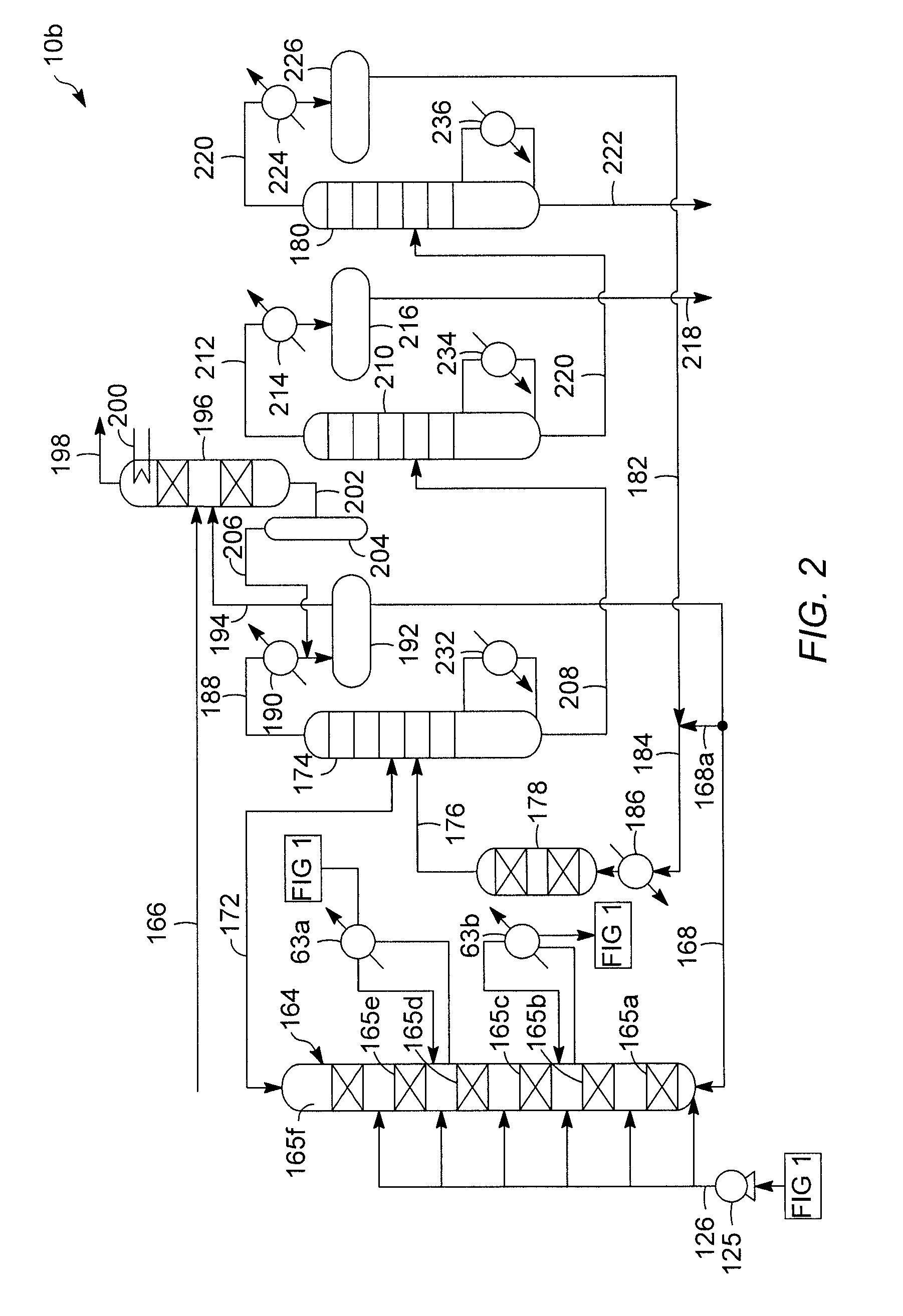
[0024]FIG. 1 schematically illustrates a system 10a for catalytic cracking a heavy hydrocarbon feedstock and obtaining light olefins via absorption-based product recovery and FIGS. 2 and 3 schematically illustrate systems 10b, 10c for efficiently converting the light olefins from the system 10a into one or more useful intermediates. Those skilled in the art and guided by the teachings herein provided will recognize and appreciate that the illustrated systems 10a, 10b, 10c have been simplified by eliminating some usual or customary pieces of process equipment including some heat exchangers, process control systems, pumps, fractionation systems, and the like. It may also be discerned that the process flows depicted in FIGS. 1-3 may be modified in many aspects without departing from the basic overall concepts disclosed herein.

[0025]In the cracking system 10a, a suitable heavy hydrocarbon feedstock stream is introduced via a line 12 into a fluidized reactor zone 14 wherein the heavy hyd...


PUM

PropertyMeasurementUnit
Temperatureaaaaaaaaaa
Fractionaaaaaaaaaa
Fractionaaaaaaaaaa

Abstract

Processing schemes and arrangements are provided for obtaining ethylene and ethane via the catalytic cracking of a heavy hydrocarbon feedstock and converting the ethylene into ethyl benzene without separating the ethane from the feed stream. The disclosed processing schemes and arrangements advantageously eliminate any separation of ethylene from ethane produced by a FCC process prior to using the combined ethylene / ethane stream as a feed for an ethyl benzene process. Further, heat from the alkylation reactor is used for one of the strippers of the FCC process and at least one bottoms stream from alkylation process is used as an absorption solvent in the FCC process.

Description

TECHNICAL FIELD[0001]This disclosure relates generally to hydrocarbon processing. More specifically, this disclosure relates to the initial processing of hydrocarbon-containing materials into an intermediate stream of ethane and ethylene, produced by the cracking of a heavy hydrocarbon feedstock. This disclosure also relates to the subsequent use of said intermediate stream in the making of valuable aromatics, such as ethyl benzene.BACKGROUND OF THE RELATED ART[0002]Light olefins serve as feed materials for the production of numerous chemicals. Light olefins have traditionally been produced through the processes of steam or catalytic cracking of hydrocarbons derived from petroleum sources. Fluidized catalytic cracking (FCC) of heavy hydrocarbon streams is commonly carried out by contacting relatively high boiling hydrocarbons with a catalyst composed of finely divided or particulate solid material. The catalyst is transported in a fluid-like manner by transmitting a gas or vapor thr...

Claims


Application Information

Patent Timeline
IPC IPC(8): C07C4/06C07C2/72
CPCC07C2/66C10G55/06C10G67/04Y10S585/91C10G69/04C07C15/073C10G11/18
Inventor SCHULTZ, MICHAEL A.
Owner UOP LLC
Why Eureka
Eureka Blog
Learn More