
Methods, Systems, And Devices For Deep Desulfurization Of Fuel Gases

Active Publication Date: 2009-05-07
BATTELLE MEMORIAL INST
View PDF1 Cites 14 Cited by
  • Summary
  • Abstract
  • Description
  • Claims
  • Application Information

AI Technical Summary

Benefits of technology

[0005]The present invention is a highly effective and regenerable method, system and device that enables the deep desulfurization of warm fuel gases by passing these warm gasses over metal-based sorbents arranged in a mesoporous substrate. This technology protects Fischer-Tropsch synthesis catalysts and other sulfur sensitive catalysts, without drastic cooling of the fuel gases, and without sintering or agglomeration of the metal sorbents during the regeneration process. This allows for much more energy efficient processes for deep desulfurization to be designed. The system is characterized by active metal-based sorbents such as transient metals like Cr, Fe, Co, Ni, Cu, Ru, Rh, Pd, Ag, Pt, Au and mixtures and alloys thereof that are attached to a porous substrate, particularly a mesoporous silicate such as SBA-16.
[0010]The present invention enables deep desulfurization of warm gasses. The mesoporous structures described prevent metal particle agglomeration and pore blocking, and maintaining access to the active metal sites. These nanostructured sorbents can reduce the sulfur concentration from warm fuel gases to well below 50 ppb, and can be repeatedly regenerated using a combined oxidation and reduction process.

Problems solved by technology

Most syngases contain impurities that may make it unsuitable for various end uses.
Sulfur-containing molecules, primarily H2S and COS, are especially troublesome catalyst poisons that must be removed to the parts per billion levels for the production of fuels and chemicals.
Although technical approaches exist for removal of these sulfur species, these approaches typically tend to be rather costly, require temperature fluctuations, and in many cases backup sacrificial adsorbents.
Since catalytic processes for the production of fuels and chemicals typically operate in the range of 225-300° C., a process that requires the cooling of syngas followed by a re-heating is energy inefficient.
This results in a loss of surface area and therefore sulfur adsorbent capacity.

Method used


Image

  • Methods, Systems, And Devices For Deep Desulfurization Of Fuel Gases
  • Methods, Systems, And Devices For Deep Desulfurization Of Fuel Gases
  • Methods, Systems, And Devices For Deep Desulfurization Of Fuel Gases

Examples


Embodiment Construction

[0023]The following description includes the preferred best mode of one embodiment of the present invention. It will be clear from this description of the invention that the invention is not limited to these illustrated embodiments but that the invention also includes a variety of modifications and embodiments thereto. Therefore the present description should be seen as illustrative and not limiting. While the invention is susceptible of various modifications and alternative constructions, It should be understood, that there is no intention to limit the invention to the specific form disclosed, but, on the contrary, the invention is to cover all modifications, alternative constructions, and equivalents falling within the spirit and scope of the invention as defined in the claims.

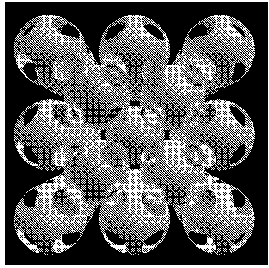
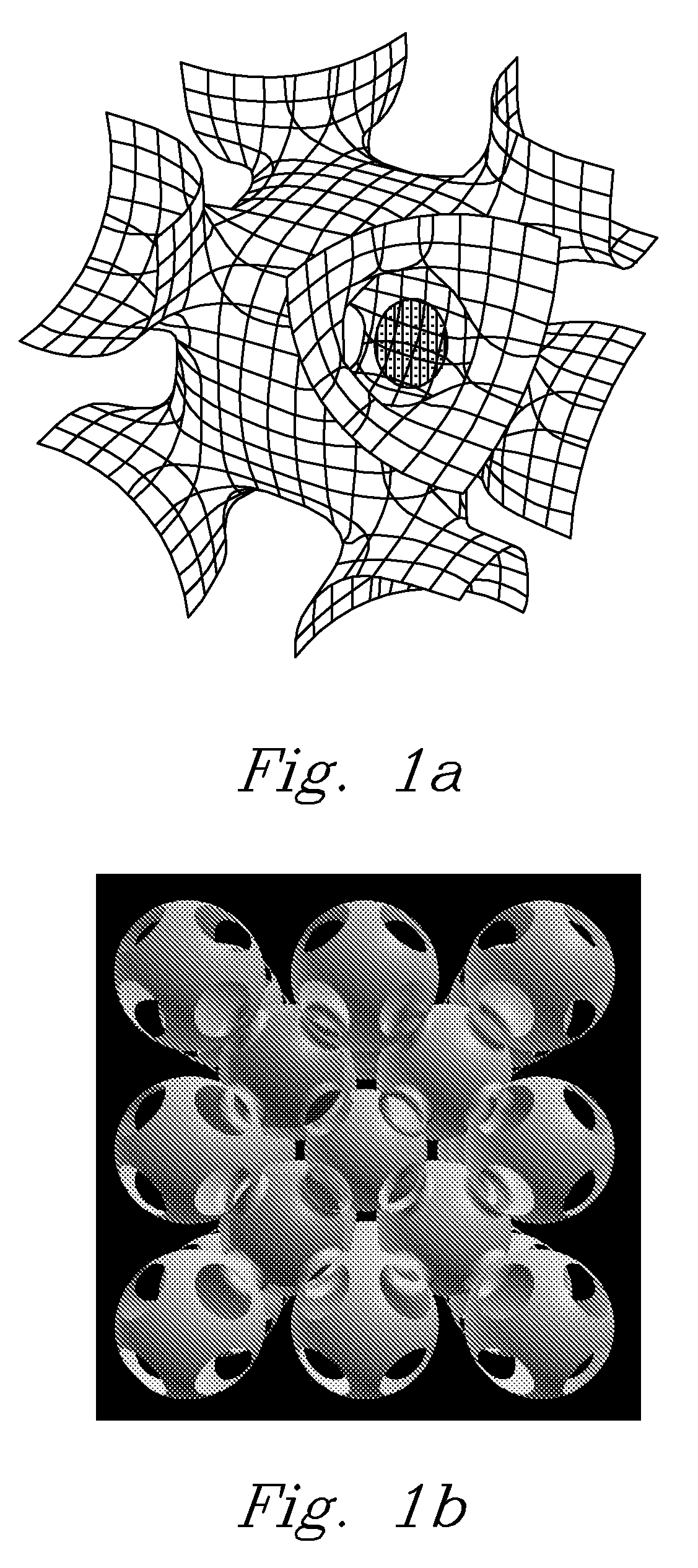
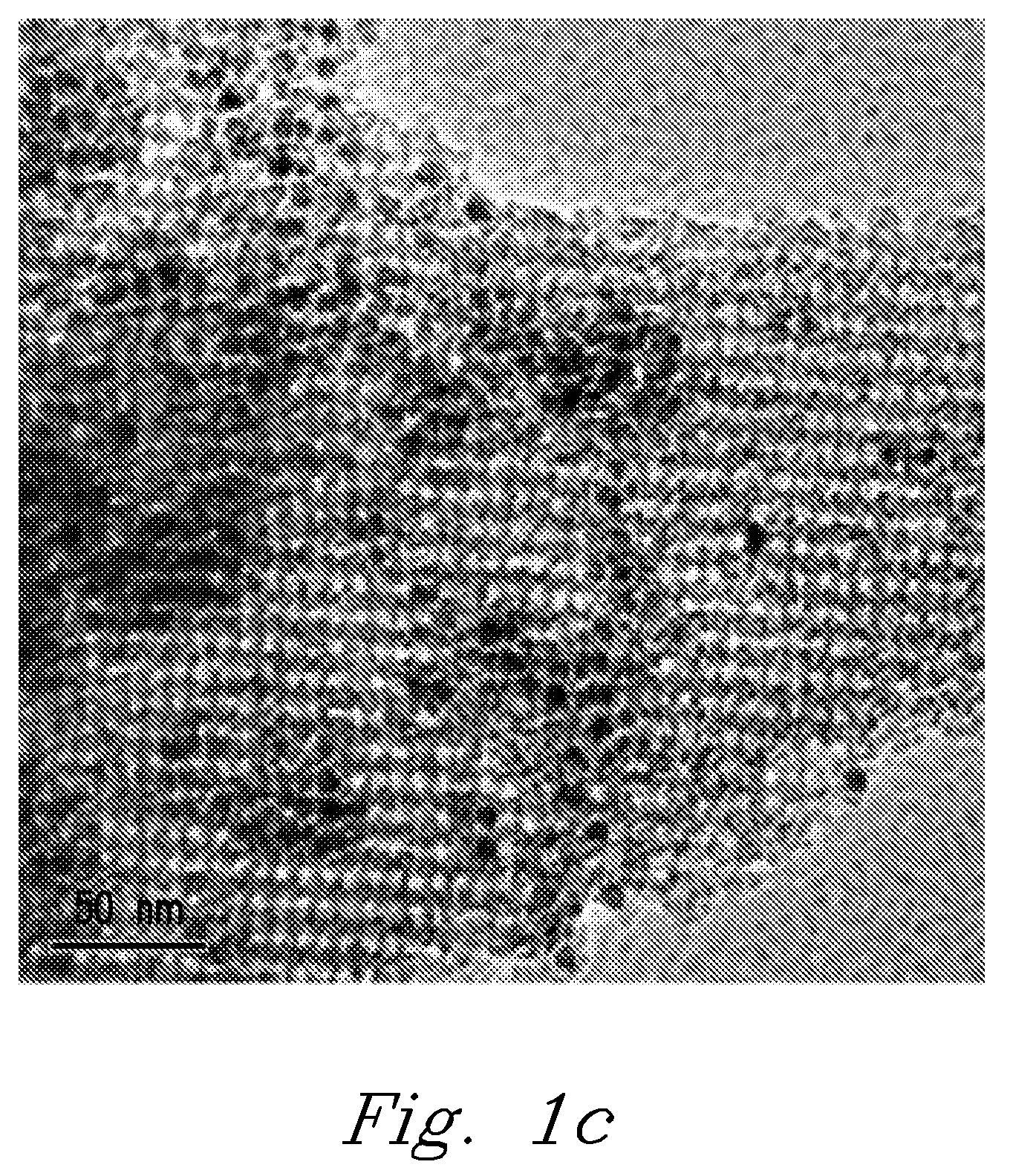
[0024]FIGS. 1-8 show a variety of embodiments of the present invention. Referring first to FIGS. 1A and 1B, schematic views of one embodiment of the present invention is shown. In the first preferred embodim...


PUM

PropertyMeasurementUnit
Temperatureaaaaaaaaaa

Abstract

A highly effective and regenerable method, system and device that enables the desulfurization of warm fuel gases by passing these warm gasses over metal-based sorbents arranged in a mesoporous substrate. This technology will protect Fischer-Tropsch synthesis catalysts and other sulfur sensitive catalysts, without drastic cooling of the fuel gases. This invention can be utilized in a process either alone or alongside other separation processes, and allows the total sulfur in such a gas to be reduced to less than 500 ppb and in some instances as low as 50 ppb.

Description

FEDERALLY-SPONSORED RESEARCH AND DEVELOPMENT[0001]This invention was made with Government support under Contract DE-AC0576RLO1830 awarded by the U.S. Department of Energy. The Government has certain rights in the invention.BACKGROUND OF THE INVENTION[0002]Syngas generated by the gasification of coal or biomass has many potential applications, including the production of hydrocarbon transportation fuels, chemicals (including hydrogen), and electric power. Most syngases contain impurities that may make it unsuitable for various end uses. Sulfur-containing molecules, primarily H2S and COS, are especially troublesome catalyst poisons that must be removed to the parts per billion levels for the production of fuels and chemicals. Although technical approaches exist for removal of these sulfur species, these approaches typically tend to be rather costly, require temperature fluctuations, and in many cases backup sacrificial adsorbents. Since catalytic processes for the production of fuels ...

Claims


Application Information

Patent Timeline
IPC IPC(8): B01D53/14B01J20/02B01J20/10
CPCB01D53/02B01J20/28083B01D2253/112B01D2253/30B01D2257/30B01D2257/304B01D2257/306B01D2257/308B01D2258/06B01D2259/40083B01D2259/4009C01B3/56C01B2203/043C01B2203/048C01B2203/0485C10K1/32C10L3/10B01J20/06B01J20/28097B01J20/3204B01J20/3236B01J20/3458B01J20/3483B01J20/0225B01J20/0233B01J20/103B01D2253/106B01D53/48
Inventor LI, LIYUKING, DAVID L.LIU, JUNHUO, QISHENG
Owner BATTELLE MEMORIAL INST
Learn More