Engine cooling medium circulation device

a circulation device and cooling medium technology, applied in the direction of machines/engines, mechanical devices, non-fuel substance addition to fuel, etc., to achieve the effect of avoiding excessive egr gas cooling, simple device configuration, and effectively avoiding emission degradation

Inactive Publication Date: 2009-05-07
TOYOTA JIDOSHA KK
View PDF6 Cites 44 Cited by
  • Summary
  • Abstract
  • Description
  • Claims
  • Application Information

AI Technical Summary

Benefits of technology

[0040]When the above configuration is employed, the temperature of the cooling medium supplied to the EGR cooler is raised at the time of an ultracold start to avoid excessive EGR gas cooling. This enables a simple device configuration to effectively avoid emission degradation that may occur when a low-temperature EGR gas is introduced into a combustion chamber.

Problems solved by technology

As regards the EGR cooler, it is desired that the generation of NOx be inhibited by cooling the EGR gas; however, excessive EGR gas cooling will lead to the generation of HC and the like.

Method used


Image

  • Engine cooling medium circulation device
  • Engine cooling medium circulation device
  • Engine cooling medium circulation device

Examples


Embodiment Construction

[0046]An embodiment of the present invention (an embodiment that is considered to be the best by the applicant at the time of application of the present invention) will now be described with reference to the accompanying drawings.

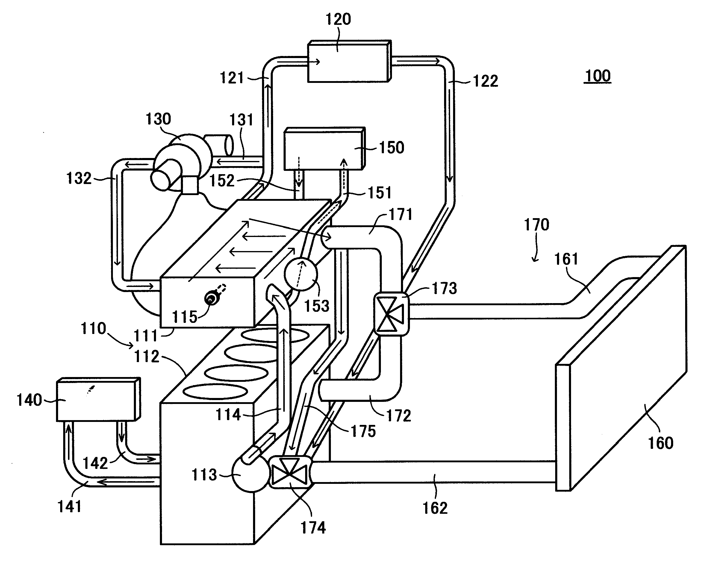
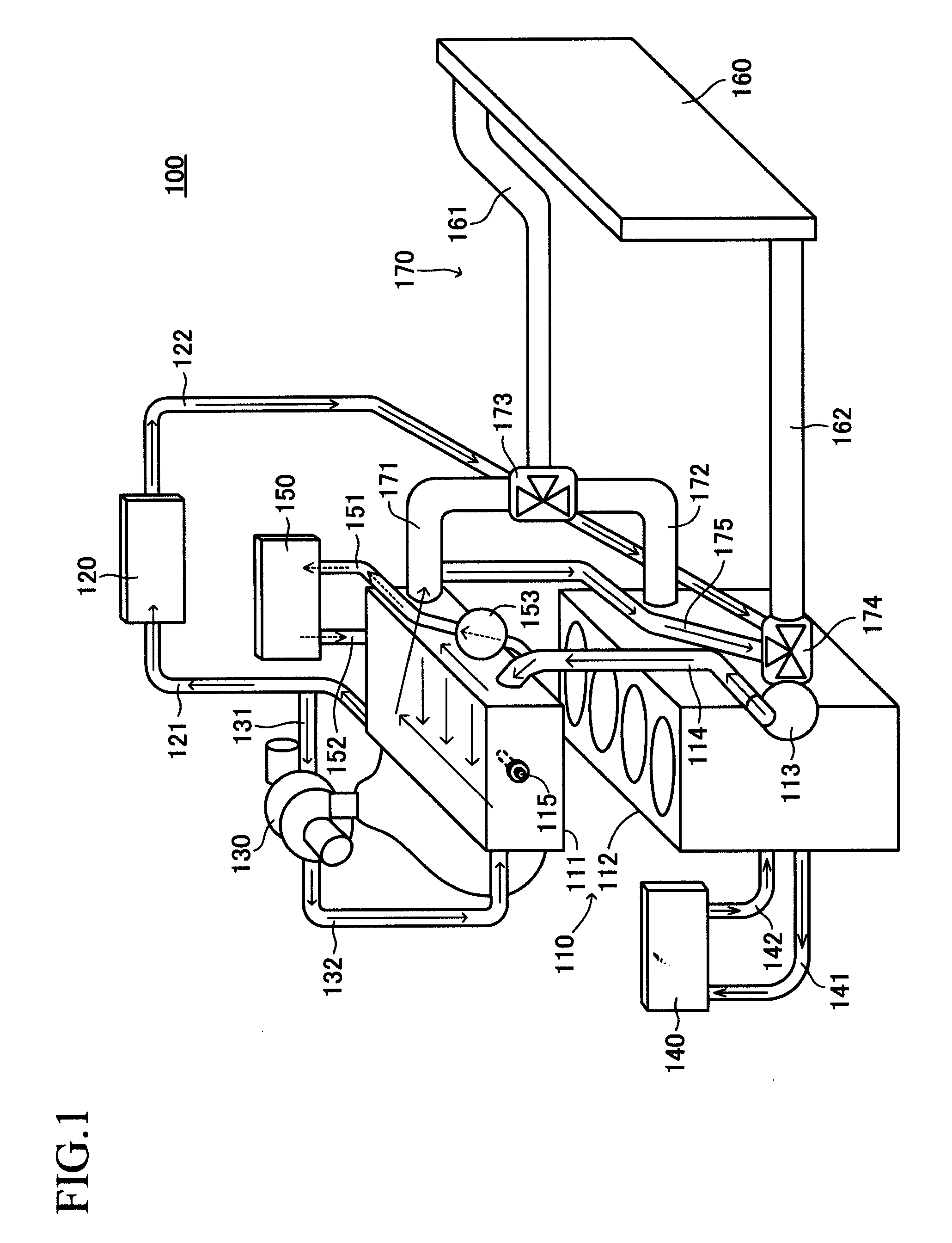
[0047]FIG. 1 is a schematic diagram illustrating a cooling water circulation system 100 according to an embodiment of the present invention.

[0048]The cooling water circulation system 100 includes an engine block 110, a heater 120, a turbocharger 130, an oil cooler 140, an EGR cooler 150, a radiator 160, and an engine block cooling switching section 170.

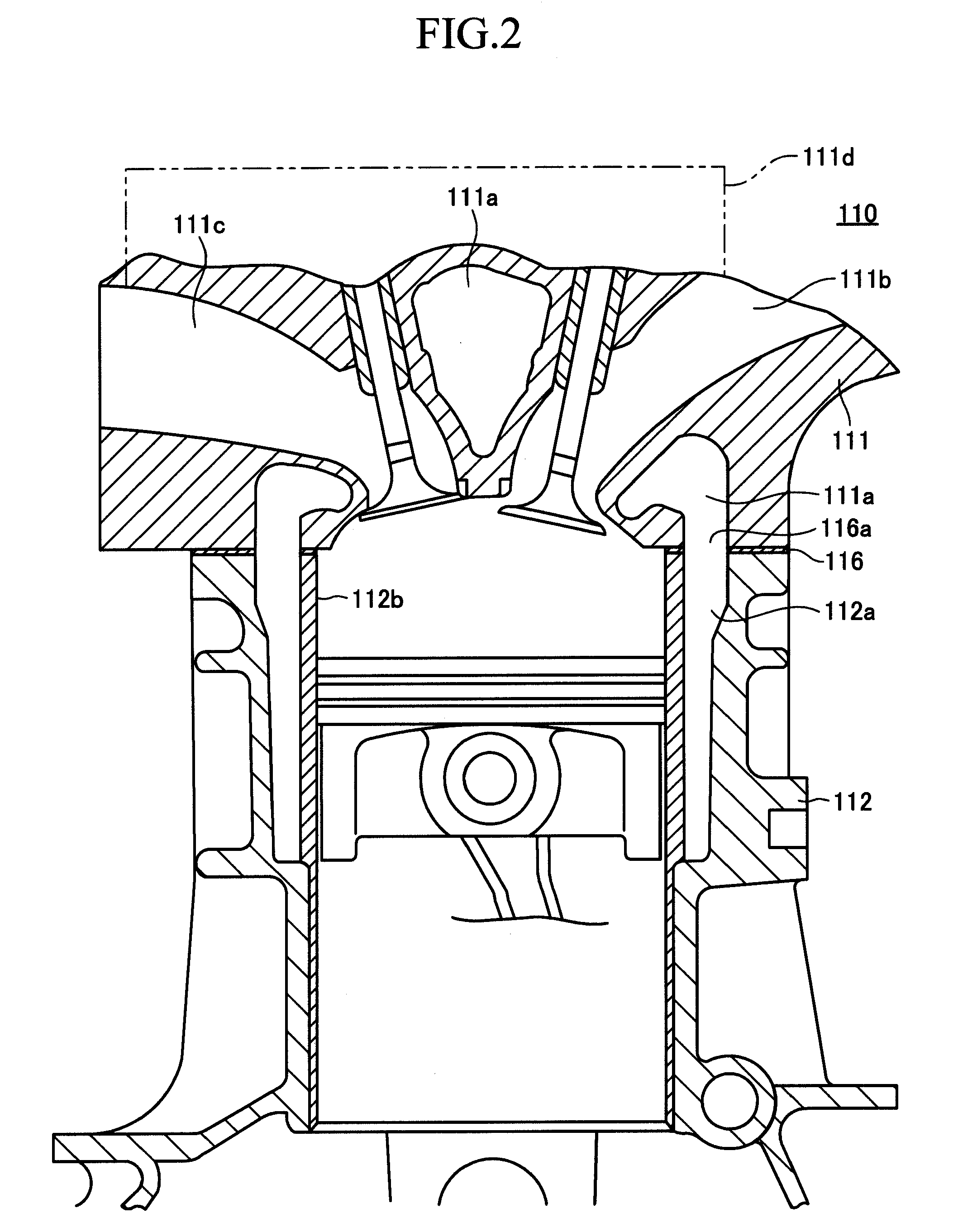
[0049]The engine block 110 includes a cylinder head 111 and a cylinder block 112. The lower lateral side of the cylinder block 112 is provided with a water pump 113, which causes cooling water to circulate in the cooling water circulation system 100. A cooling water outlet of the water pump 113 is connected to one end of a pump delivery pipe 114. The other end of the pump delivery pipe 114 is connected to the...


PUM


Abstract

A cooling water circulation system (100) is configured so that cooling water is delivered from a water pump (113) toward a cylinder head (111) via a pump delivery pipe (114). Further, the system (100) is configured so that an engine block cooling switching section (170) changes the supply of the cooling water from the cylinder head (111) to a cylinder block (112) in accordance with a cooling water temperature. An EGR cooler branch pipe (151), which branches off from the pump delivery pipe (114), is connected to an EGR cooler (150). The EGR cooler branch pipe (151) is provided with an EGR cooler cooling switching valve (153) that opens or closes in accordance with an operating state.

Description

BACKGROUND OF THE INVENTION[0001]1. Technical Field[0002]The present invention relates to a device that is configured to circulate a cooling medium for an engine (hereinafter simply referred to as the “circulation device”).[0003]2. Background Art[0004]Conventional circulation devices having various configurations are known. For example, the configurations disclosed by Japanese Patents JP-A No. 140701 / 2001, JP-A No. 147292 / 2002, and JP-A No. 227646 / 2002 cool an EGR gas by circulating cooling water, which is introduced from a circulation path for engine cooling water, into an EGR cooler and exchanging heat between the cooling water and EGR gas. Here, an EGR (exhaust gas recirculation) technology is used to purify an exhaust gas of a diesel engine or the like. That is, in the EGR technology, part of the exhaust gas is recirculated to intake air to reduce the amount of NOx in the exhaust gas. This reduces the combustion temperature and inhibits the generation of NOx.SUMMARY OF THE INVEN...

Claims


Application Information

Patent Timeline
Patent Type & Authority Applications(United States)
IPC IPC(8): F01P5/10F02M25/07
CPCF01P3/02F01P7/16Y02T10/121F02M25/0706F02M25/0731F01P7/165F02M26/04F02M26/28
Inventor HAYASHI, KUNIHIKO
Owner TOYOTA JIDOSHA KK
Why Eureka
Try Eureka