
Solar cell sheet and a method for the preparation of the same

a technology of solar cells and solar energy, applied in solar heat collectors, solar heat systems, heat generation devices, etc., can solve the problems of insufficient supply, low transmittance, and impending need for new energy resources to replace petroleum fossil fuels, and achieve the effect of improving light trapping ability

Inactive Publication Date: 2009-05-07
EI DU PONT DE NEMOURS & CO
View PDF9 Cites 47 Cited by
  • Summary
  • Abstract
  • Description
  • Claims
  • Application Information

AI Technical Summary

Benefits of technology

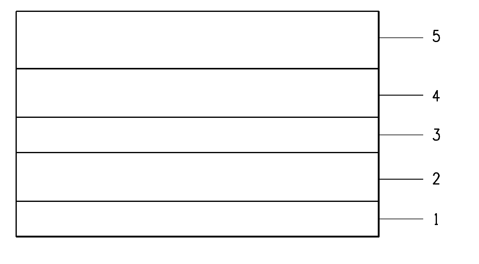
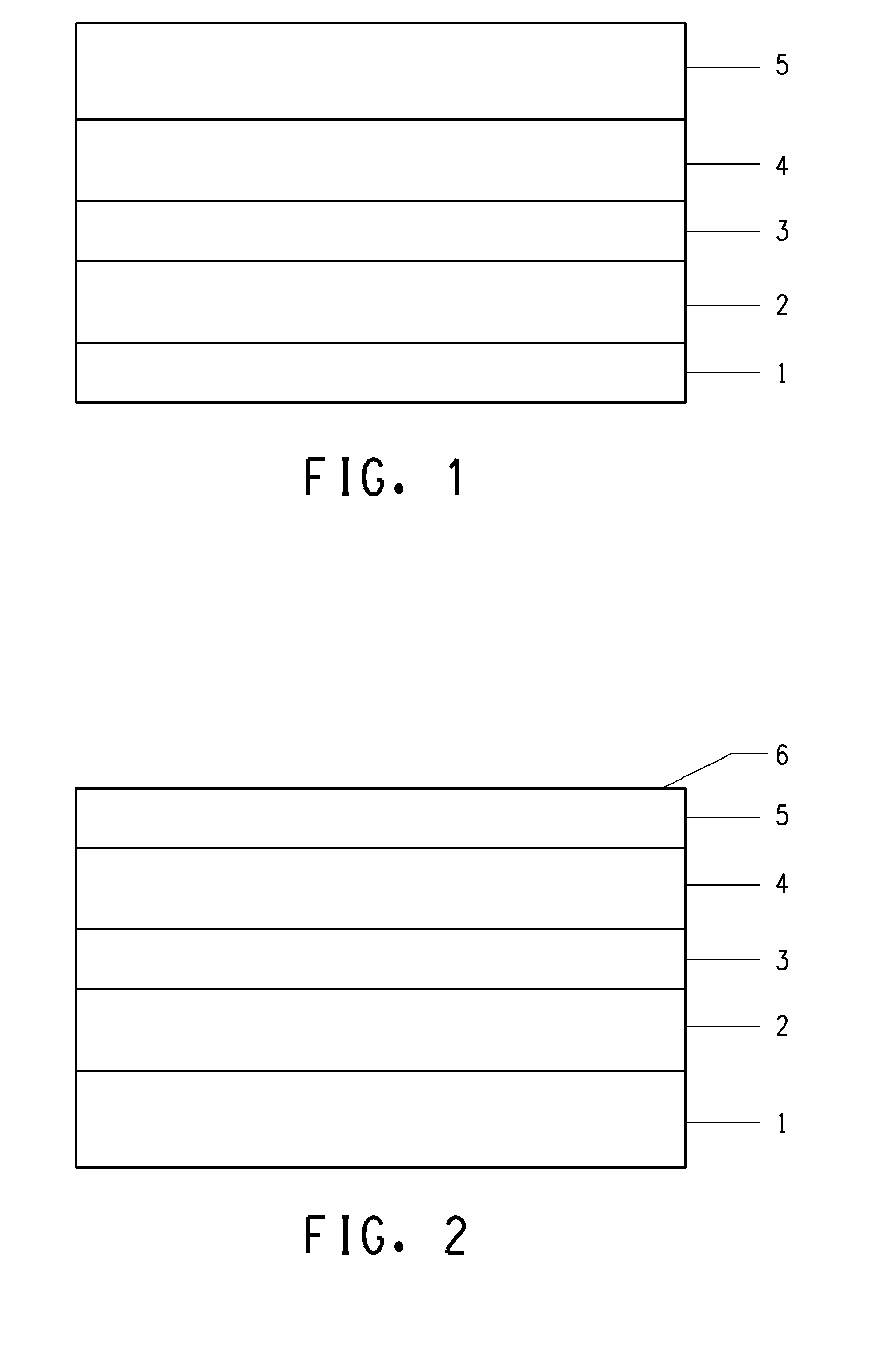
[0011]The first part of the present invention provides a solar cell sheet, comprising a back sheet, a front sheet, and a solar cell circuit between the back sheet and the front sheet. The front sheet has the light receiving first surface and the second surface adjacent to The circuit of the solar cell, wherein the characteristics comprising the second surface has a surface texture which can improve light trapping ability.
[0016]Forming a surface texture capable of improving the light trapping property on the second surface of the front sheet, and
[0021]Forming a surface texture capable of improving the light trapping property on the second surface of the back sheet, and

Problems solved by technology

Therefore, seeking new energy resources to replace petroleum fossil fuel has become an imminent problem that needs to be addressed immediately.
Moreover, it is inexhaustible in supply and always available for use.
However, the disadvantages of glass are that compared with many plastic materials, its transmittance is lower, it is heavier, its impact strength is worse, and special care must be taken less it breaks during transportation, installation, and application.
For example, in a severe weather, e.g, hail, the exposed front sheet may be broken due to the impact.
Although plastic materials as front sheet have high normal light transmittance, when the incident angle of sunlight is relatively high, the untreated plastic materials have relatively worse light trapping property.
Thus, it limits the sunlight utilization efficiency.
Therefore, there is still a lot of room for improving the output power of the solar cell using plastic materials as the front sheet.
Although typical back sheet of a solar cell can meet the above mentioned typical requirements, there is still a lot of room for improving the sunlight utilization efficiency.

Method used


Image

  • Solar cell sheet and a method for the preparation of the same
  • Solar cell sheet and a method for the preparation of the same
  • Solar cell sheet and a method for the preparation of the same

Examples


example 1

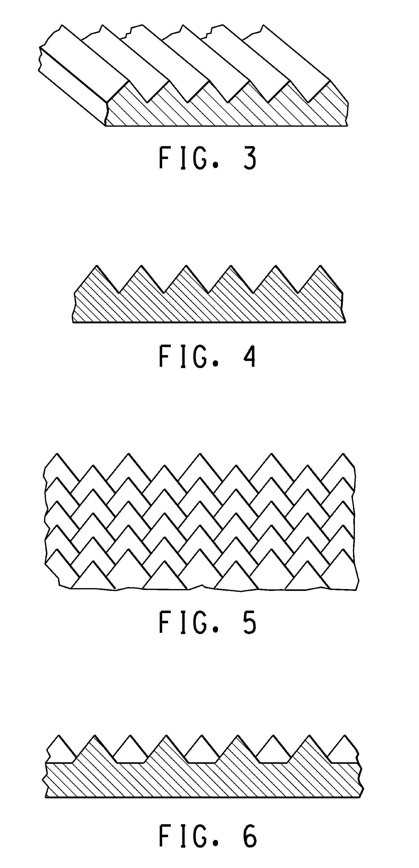
[0108]Obtained a perfluoroethylene-perfluoropropylene copolymer sheet (with 50 μm thick, Teflon® DuPont, United States). The copolymer was extruded through a NRM extruder of Davis-Standard Corporation Limited (diameter 4.5 in. and aspect ratio 20:1). Then, it was stretched to a film with thickness of 50 μm by passing through a T shaped molder head (width 100 in.) of a center feeding produced by Dupont company of the United States followed by passing through a roller with a smooth surface at room temperature and then a roller gin of BGE Corporation of the United States at 200° C. to form a surface texture with a tetrahedron pyramidal shape on one of its surfaces. The surface texture was evenly distributed on the copolymer surface. The distribution density was 1.0×10⁶ pieces / cm2. The height of a single tetrahedron pyramid was 5.0 μm. The length of the base side was 10 μm. The distance of the top points of two adjacent pyramids was 10 μm.

[0109]The above method was used to measure the r...

example 2

[0121]Obtained a perfluoroethylene-perfluoropropylene copolymer sheet (with 50 □m thick, Teflon® DuPont, United States). The copolymer was extruded through a NRM extruder of Davis-Standard Corporation Limited (diameter 4.5 in. and aspect ratio 20:1). Then, it was stretched to a film with thickness of 50 μm by passing through a T shaped molder head (width 100 in.) of a center feeding produced by Dupont Company of the United States followed by passing through a roller with a smooth surface at room temperature. A layer of hollow glass microbeads was evenly coated on one surface of the copolymer sheet by painting. The distribution density was 2.3×10⁵ pieces / cm2. The mean diameter of the microbeads was 18 μm with the standard deviation of 4 μm.

[0122]The above method was used to measure the reflectance of the second surface with a surface texture and the result was 5.6%.

[0123]Obtained a glass (tempered glass, purchased from Dongguan Nanbo Solar Energy Glass Corporation of P.R. China, thic...

example 3

[0129]Obtained a perfluoroethylene-perfluoropropylene copolymer sheet (with 50 □m thick, Teflon® DuPont, United States). The copolymer was extruded through a NRM extruder of Davis-Standard Corporation Limited (diameter 4.5 in. and aspect ratio 20:1). Then, it was stretched to a film with thickness of 50 μm by passing through a T shaped molder head (width 100 in.) of a center feeding produced by EDI company of the United States followed by passing through a roller with a smooth surface at room temperature and then a roller gin of BGE Corporation of the United States at 200° C. to form a surface texture with hemispheric shape on one of its surfaces. The surface texture was evenly distributed on the entire surface of the copolymer sheet. The distribution density was 1.0×10⁶ pieces / cm2. The height of a single hemisphere was 5.0 μm. The diameter of the base side was 10 μm. The distance of the top points of two adjacent hemispheres was 10 μm.

[0130]The above method was used to measure the ...


PUM


Abstract

The present invention discloses a solar cell sheet, comprising a back sheet, a plastic front sheet and a solar cell circuit between the back sheet and the plastic front sheet, wherein the plastic front sheet possesses a first light receiving surface and a second surface adjacent to the solar cell circuit, wherein the second surface possesses a surface texture capable of improving light trapping property. It also discloses a method for the preparation of the same.

Description

[0001]This application claims the benefit of China application number 200710166978.5, filed Nov. 7, 2007 which is herein incorporated by reference.FIELD OF THE INVENTION[0002]The present invention relates to a novel type of solar cell sheet, which possesses high output power. The present invention also relates to a method for the preparation of the novel solar cell sheet.BACKGROUND OF THE INVENTION[0003]With global warming, the government of each country places higher requirements for energy saving and pollution discharge reduction. Therefore, seeking new energy resources to replace petroleum fossil fuel has become an imminent problem that needs to be addressed immediately.[0004]Solar energy is clean and pollution free. Moreover, it is inexhaustible in supply and always available for use. Currently, the utilization of solar energy is by converting the solar energy into electrical energy through a solar cell sheet. Then the electrical energy is used to drive the devices such as an el...

Claims


Application Information

Patent Timeline
Patent Type & Authority Applications(United States)
IPC IPC(8): H01L31/00
CPCF24J2002/003Y02E10/50H01L31/048H01L31/0236H02S40/22Y02E10/52F24S2023/88
Inventor ZHAO, RUOFEIYIN, GUANGJUNYE, CHANGMING
Owner EI DU PONT DE NEMOURS & CO
Learn More