Composite of metal and resin, and method for manufacturing same
- Summary
- Abstract
- Description
- Claims
- Application Information
AI Technical Summary
Benefits of technology
Problems solved by technology
Method used
Image
Examples
embodiment 1
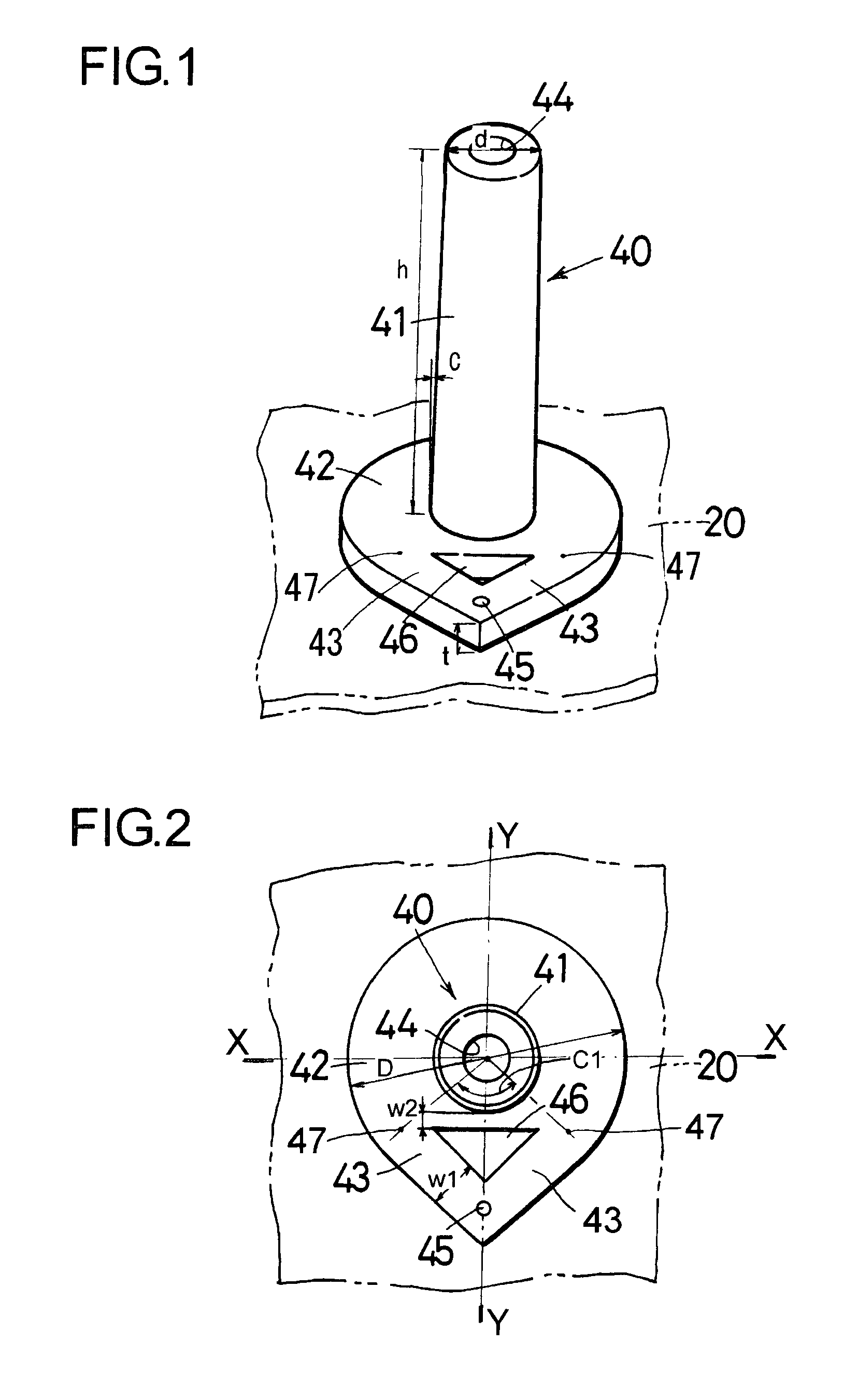
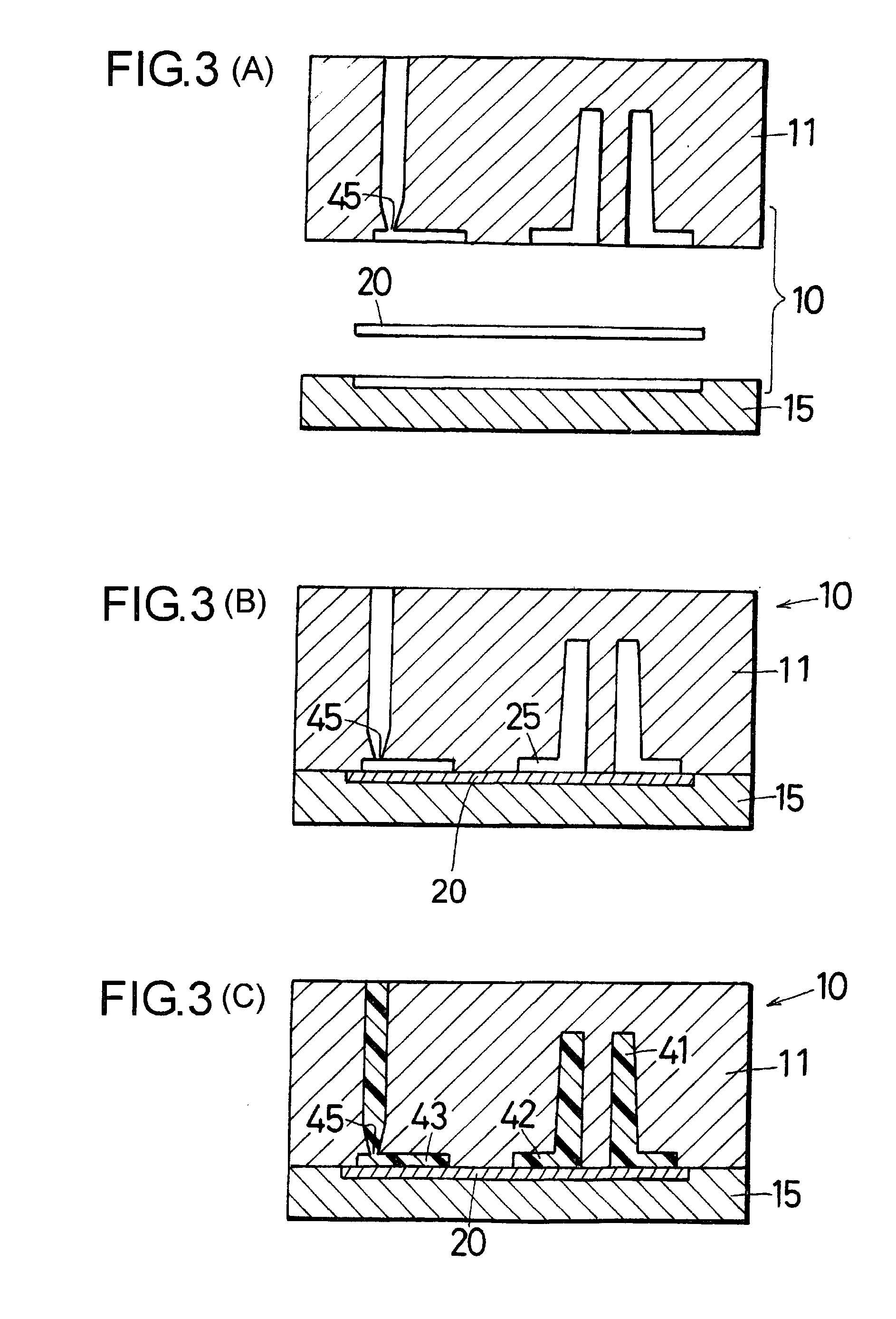
[0090]FIG. 1 is an oblique view of a composite 40 in which a shaped thermoplastic resin having an upright molding (boss) is integrated with a shaped metal by injection joining. FIG. 2 is a plan view of the composite 40. FIGS. 3A, 3B, and 3C schematically illustrate the metallic mold and steps for molding the composite 40 in which a thermoplastic resin is integrated with a shaped metal by injection joining. FIG. 3A illustrates the state when the mold is opened, FIG. 3B illustrates the state when the mold is closed and FIG. 3C illustrates the state when the thermoplastic resin is injected into the metallic mold.
[0091]A commercially available A5052 aluminum alloy sheet with a thickness of 1 mm was purchased and cut into rectangular pieces measuring 40 mm×60 mm. These aluminum alloy pieces (hereinafter referred to as aluminum pieces) were subjected to the following liquid treatment as pretreatment. A dipping jig completely covered with vinyl chloride resin was fabricated by braiding sta...
embodiment 2
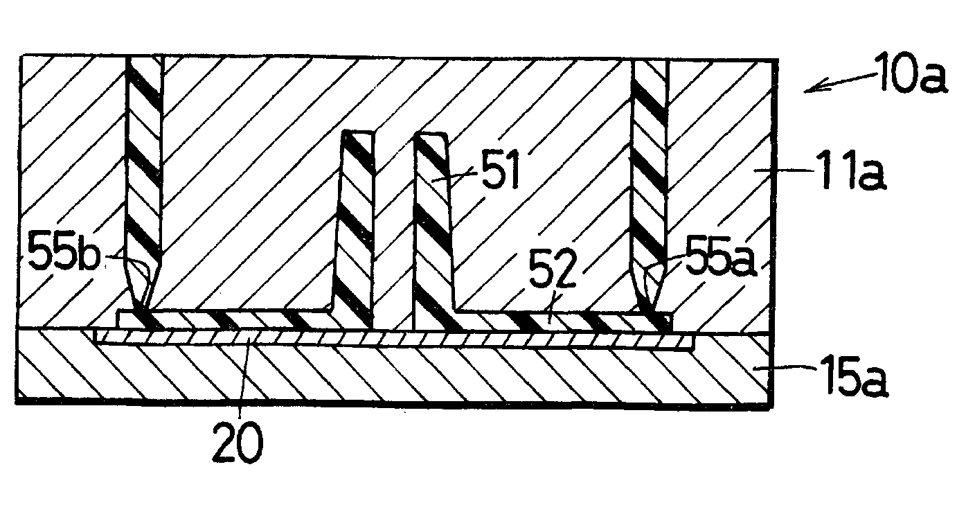
[0099]FIG. 4 is an oblique view of a composite 50 in which a shaped thermoplastic resin having a boss or the like is integrated with a shaped metal by injection joining. FIG. 5 is a plan view of the composite 50. FIGS. 6A, 6B and 6C schematically illustrate the mold and steps for molding the composite 50, in which a thermoplastic resin is integrated with a shaped metal by injection joining. FIG. 6A illustrates the state when the mold is opened, FIG. 6B illustrates the state when the mold is closed and FIG. 6C illustrates the state when the thermoplastic resin is injected into the mold.
[0100]In the following description of Embodiment 2, those components that are the same as in Embodiment 1 will be referenced with the same numbers and will not be described in detail again.
[0101]The same liquid treatment as in Embodiment 1 was performed to produce an aluminum piece 20. The mold 10a shown in FIGS. 6A, 6B and 6C was fabricated for molding a composite 50 in which the shaped resin shown in...
embodiment 3
[0105]FIG. 7 is an oblique view of a composite 30 in which a shaped thermoplastic resin is joined to a shaped metal by injection joining. FIG. 8 is a plan view of the composite 30.
[0106]The same liquid treatment as in Embodiment 1 was performed to produce an aluminum piece 20. A metallic mold was fabricated for molding a composite 30 in which the shaped resin shown in FIGS. 7 and 8 is integrated by injection joining. This metallic mold was substantially the same as that in Embodiment 1 and will therefore not be described again. The aluminum piece 20 was inserted into the metallic mold, which had been heated to 140° C. and injection joining was performed by injecting the resin through the injection gate at an injection temperature of 310° C. Approximately twenty of the composites 30 were injection molded. A hole 34 is formed in the boss 31 with its bottom being the aluminum piece 20.
[0107]A runner 33 communicates with a seat 32 through sprues 37. The sprues 37 were provided by formin...
PUM
| Property | Measurement | Unit |
|---|---|---|
| Flow rate | aaaaa | aaaaa |
| Shape | aaaaa | aaaaa |
Abstract
Description
Claims
Application Information
 - R&D
- Intellectual Property
- Life Sciences
- Materials
- Tech Scout
- Unparalleled Data Quality
- Higher Quality Content
- 60% Fewer Hallucinations
Browse by: Latest US Patents, China's latest patents, Technical Efficacy Thesaurus, Application Domain, Technology Topic, Popular Technical Reports.
© 2025 PatSnap. All rights reserved.Legal|Privacy policy|Modern Slavery Act Transparency Statement|Sitemap|About US| Contact US: help@patsnap.com


