Electric double-layer capacitor and method for manufacturing the same
- Summary
- Abstract
- Description
- Claims
- Application Information
AI Technical Summary
Benefits of technology
Problems solved by technology
Method used
Image
Examples
embodiment 1
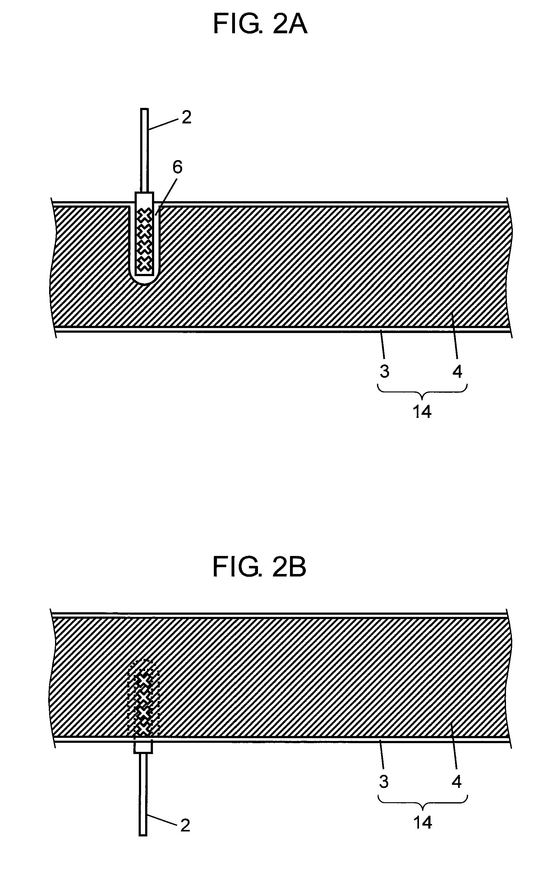
[0034]In the following, Embodiment 1 of the present invention is described with reference to FIGS. 1 to 5.
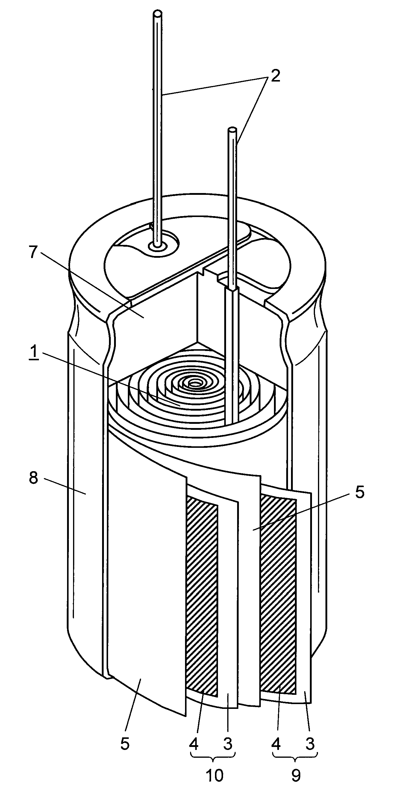
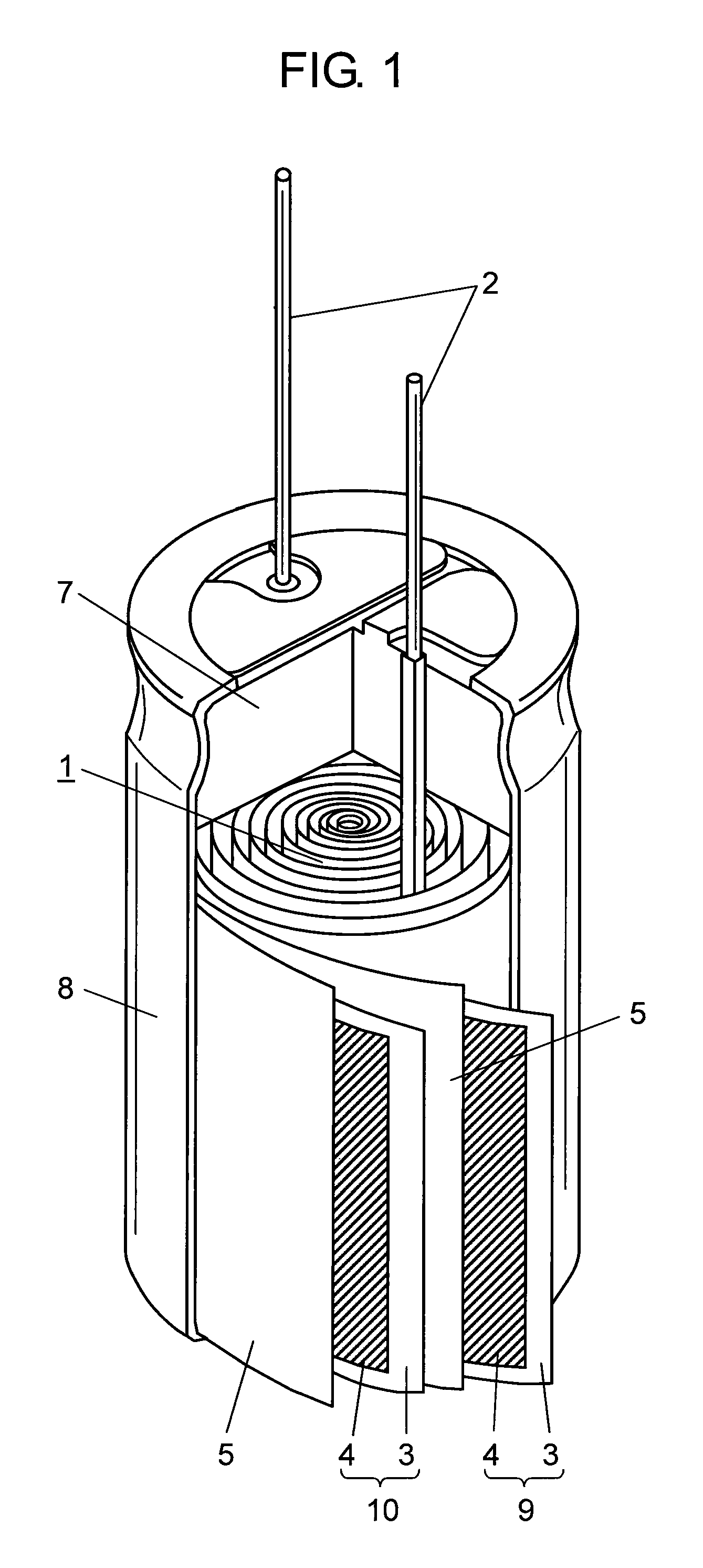
[0035]FIG. 1 is a partially broken away perspective view showing a configuration of an electric double-layer capacitor according to present Embodiment 1.
[0036]In FIG. 1, capacitor element 1 is configured such that polarizable electrode layers 4 are formed on both sides of each of two current collectors 3 made of metallic foil such as aluminum, to which lead wires 2 are connected, to give anode electrode 9 and cathode electrode 10, and these electrodes are wound with separator 5 for preventing a short circuit interposed therebetween.
[0037]It is to be noted that respective pairs of lead wires 2 and separators 5 are prepared so as to correspond to the anode and cathode electrodes.
[0038]This capacitor element 1 is impregnated with a driving electrolyte (not shown), and as shown in FIG. 1, rubber-made sealing member 7 provided with holes through which lead wires 2 are inserted is fit...
embodiment 2
[0059]In the following, Embodiment 2 of the present invention is described with reference to FIG. 6.
[0060]FIG. 6 is a partial plan view at the time when lead wire 22 is brought into contact with current collector 27 in Embodiment 2 of the present invention in a different manner from above Embodiment 1.
[0061]In FIG. 6, for connecting lead wire 22 to each of polarizable electrode layers 21 formed on both sides of current collector 27 made of metallic foil such as aluminum constituting the electrode, polarizable electrode layer 21 in a fixed position of lead wire 22 in flat section 23 is scraped away, and polarizable-electrode-layer-removed section 26 is provided. Thereafter, caulking joints 24 are formed at four points in polarizable-electrode-layer-removed section 26 and flat section 23 of lead wire 22 (two points on the end sides of electrode 20, and two points inside). Further, pressure welding joints 25 are formed at three points on a straight line connecting the caulking joints 2...
embodiment 3
[0064]In the following, the present invention is described with reference to Embodiment 3, but the present invention is not restricted to this embodiment. Further, since a configuration of an electric double-layer capacitor is the same as described in Embodiment 1 with reference to FIG. 1, a description thereof is omitted here.
[0065]FIG. 7 A is a substantial-part plan view showing a configuration of anode electrode 32 used in the same capacitor element 31, and FIG. 7 B is a sectional view of a line A-A of the same.
[0066]In FIGS. 7A and 7B, part of polarizable-electrode-layer-removed section 36 formed in anode electrode 32 (the same applies to a polarizable electrode layer formed in a cathode electrode) is removed to expose current collector 35, and to this portion where current collector 35 is exposed, anode lead wire 37 is connected by means of caulking joint and / or pressure welding joint, ultrasonic welding, etc. This removal of polarizable-electrode-layer-removed section 36 is co...
PUM
| Property | Measurement | Unit |
|---|---|---|
| Length | aaaaa | aaaaa |
| Electrical resistance | aaaaa | aaaaa |
| Width | aaaaa | aaaaa |
Abstract
Description
Claims
Application Information
 - R&D
- Intellectual Property
- Life Sciences
- Materials
- Tech Scout
- Unparalleled Data Quality
- Higher Quality Content
- 60% Fewer Hallucinations
Browse by: Latest US Patents, China's latest patents, Technical Efficacy Thesaurus, Application Domain, Technology Topic, Popular Technical Reports.
© 2025 PatSnap. All rights reserved.Legal|Privacy policy|Modern Slavery Act Transparency Statement|Sitemap|About US| Contact US: help@patsnap.com


