
Spindle Spray Coating System

a spray coating and spindle technology, applied in the field of manufacturing systems, can solve the problems of required manufacturing downtime and expensive system maintenan

Inactive Publication Date: 2009-05-21
BOYD THOMAS J
View PDF19 Cites 5 Cited by
  • Summary
  • Abstract
  • Description
  • Claims
  • Application Information

AI Technical Summary

Benefits of technology

[0010]The system of the present application provides minimization of environmental issues and significantly reduces operator exposure to highly regulated chemical materials present within a variety of coating materials, particularly adhesive and paint materials. The system contains and captures, for appropriate environmental handling, greater than 99% of the volatile organic compounds resulting from the spray application of coating materials used within the system.
[0011]The use of the present system also enables isolation and containment of overspray and spillage of the sprayed coating materials within the system, thereby protecting the spindle conveyor component transporting the products during manufacture. In the past, inadvertent contamination of conveyor system components during application of the coating materials during manufacturing has resulted in expensive system maintenance and required manufacturing downtime. The use of the spray containment component in the present system, or closed spray booth, reduces or eliminates such conveyor system contamination. The closed spray booth provides at least seven barriers to protect system components from contamination by the materials being applied during operation of the present manufacturing system. The present system provides fresh air into the closed spray booth component of the system, and removes all fumes from the entire system for any necessary further processing. Also, a quick change cleaning feature of the spray booth allows all plastic panels forming the booth to be quickly removed and replaced.
[0012]The spindle spray coating system of the present application provides reduced cycle times in order to increase product throughput by indexing and spraying multiple spindles per cycle. The present system is equipped to index at a rate of 2 parts per 1-2.5 seconds. Reduced labor costs are also obtained by improving the automation and adjustment quality of the spray system component. In particular, multiple spray guns, for example two or four, may be provided within each closed spray booth, and adjustment of each gun is provided in at least 3 axes: horizontal, vertical and an angular adjustment of approximately 60 degrees. It is understood that a smaller scale system may also be provided making use of one adjustable spray gun within the closed spray booth. A control system is also provided to electronically monitor each spindle for quality control purposes to ensure that products being manufactured are rotating properly during the spraying operation.
[0014]Following the final coating process, a substantially closed return conveyor is also provided as a portion of the spindle conveyor system. The return conveyor enables drying of the manufactured parts being coated and return of the parts for removal to a finished part conveyor. Additionally, the return conveyor uses re-circulated air from within the system. The system provides flexibility to the manufacturing process, since modules may be added, changed or removed as needed.

Problems solved by technology

In the past, inadvertent contamination of conveyor system components during application of the coating materials during manufacturing has resulted in expensive system maintenance and required manufacturing downtime.

Method used


Image

  • Spindle Spray Coating System
  • Spindle Spray Coating System
  • Spindle Spray Coating System

Examples


Embodiment Construction

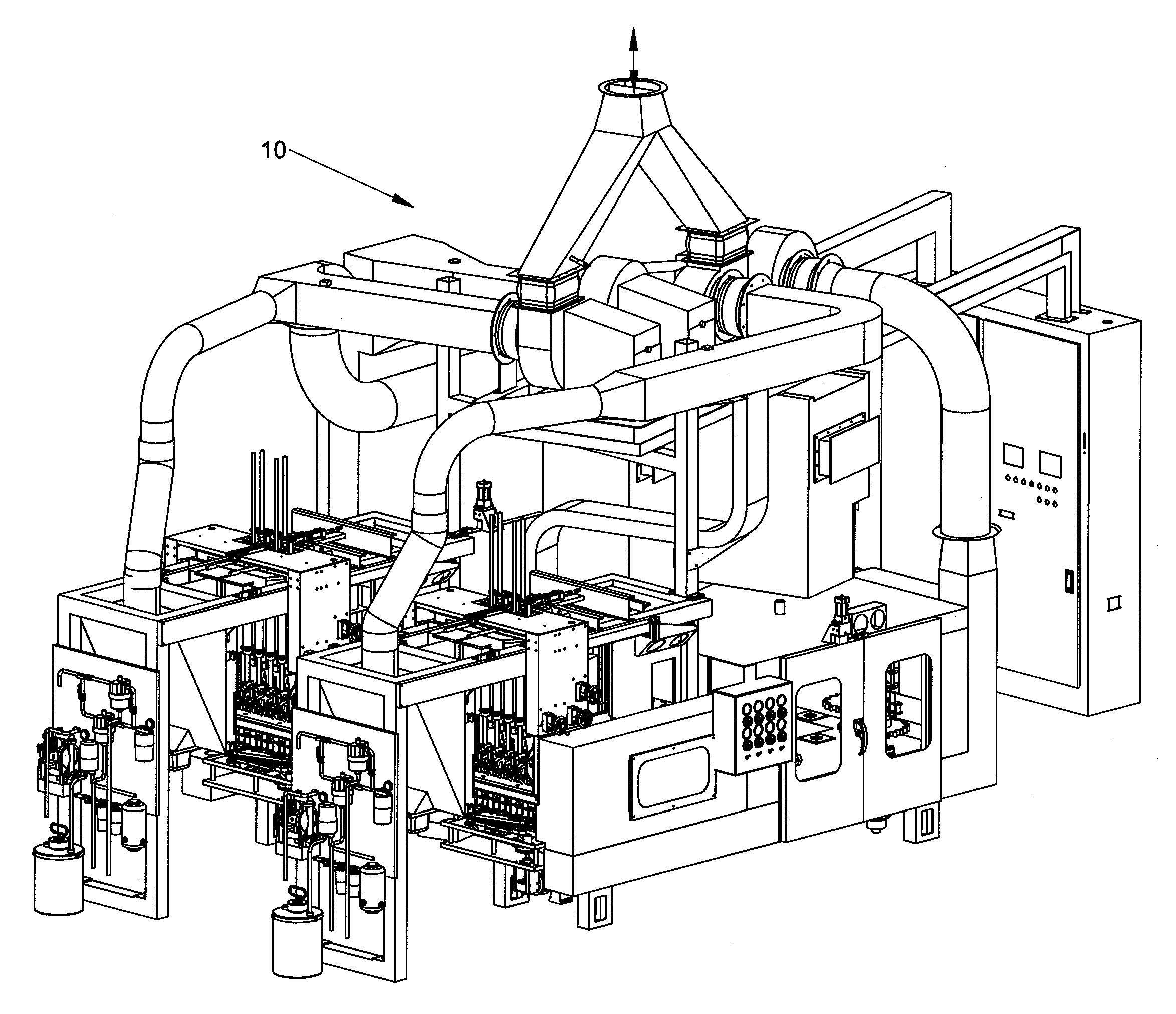
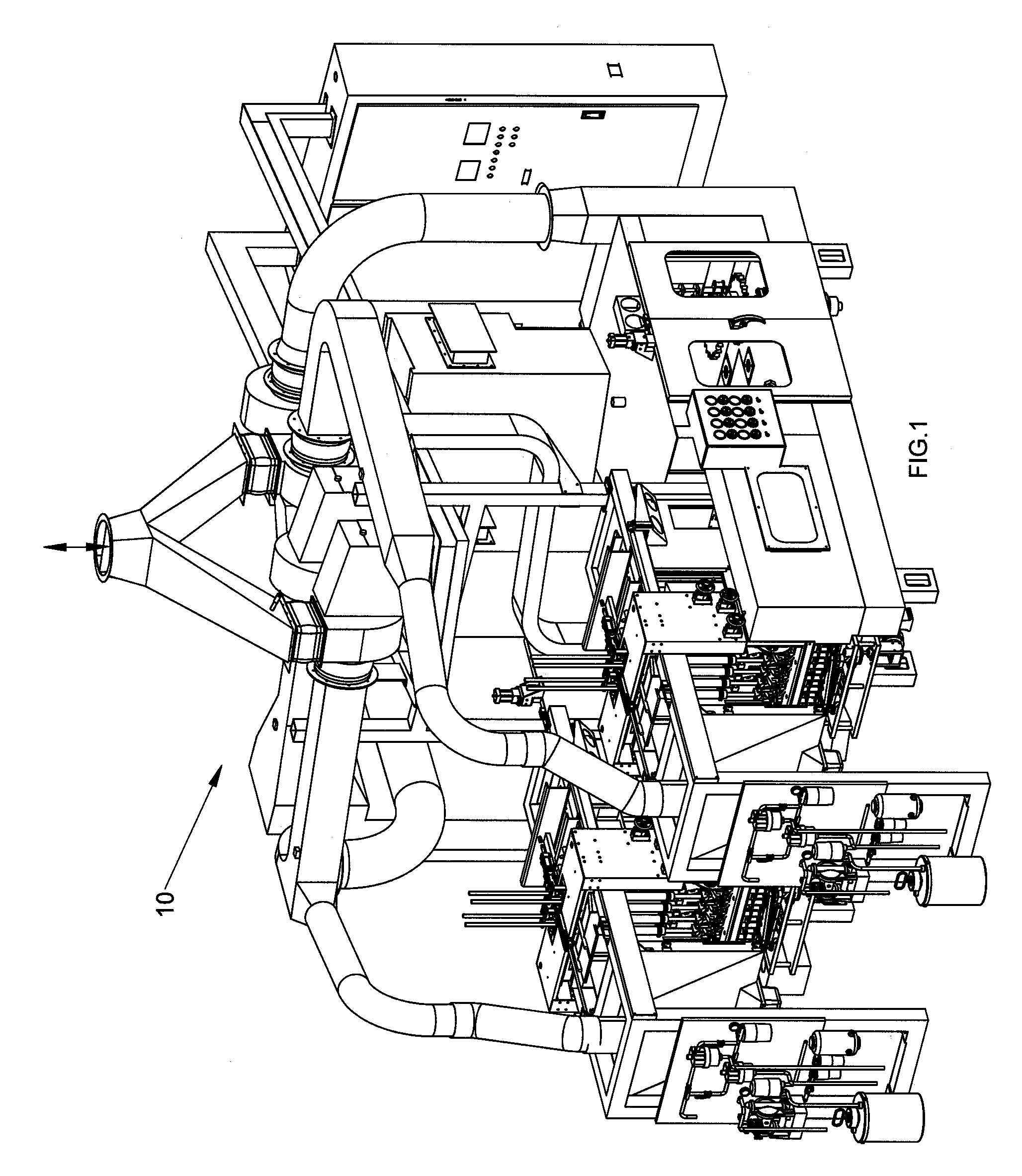
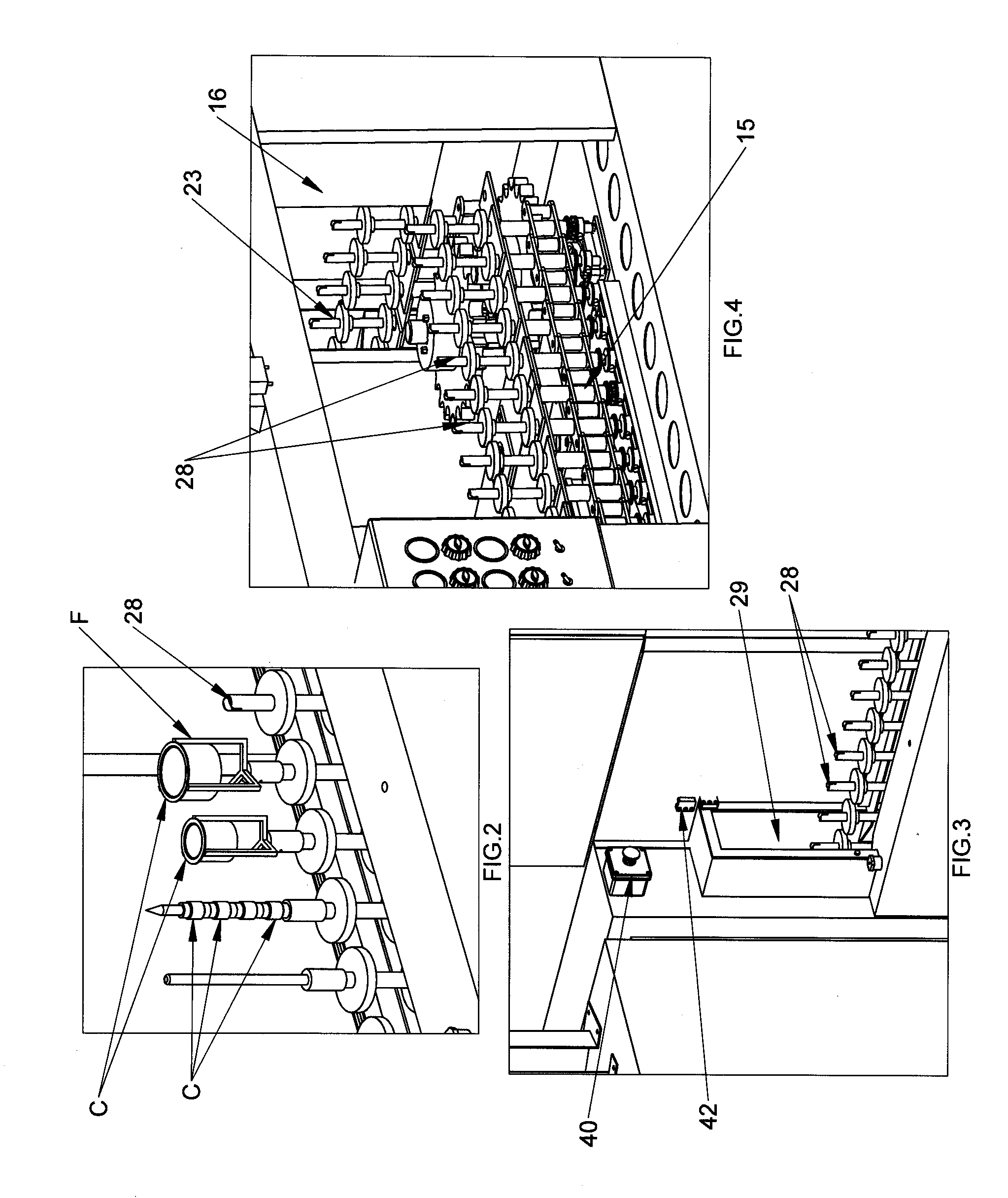
[0049]Turning now to the illustrations of the embodiments of the system of the present application, a multi-station manufacturing system 10, shown in FIGS. 1, 21, and 35a to 35d, provides flexibility and improved coating material control in the coating processes used in connection with completion of the items to be manufactured C. The system 10 is supported on a modular frame 11 and includes work stations positioned along a conveyor system 25 which continuously feeds items C to be coated.

[0050]All system operations are automatic and controlled by a Mitsubishi Q series programmable logic controller and a Mitsubishi E1100 series operator interface. Additionally, a variety of other system controllers may also be used, for example, IEC style pushbutton switches, and Guard Master safety relays and emergency stop buttons, as well as other conventional controllers, all of which are well known to one of ordinary skill in the art and are collectively referred to herein as the central control...


PUM


Abstract

A spindle spray coating system including a spindle conveyor system for horizontally transporting parts supported on spindles within the system. A spindle rotation station assembly is also provided for rotating individual spindles supporting parts during spraying. A spray containment closed spray booth for containment of parts supported on spindles during the spray operation by an adjustable spray system to minimize environmental and operator exposure to the coating materials being sprayed. A second spray containment closed spray booth may also be provided for containment of parts supported on spindles during a secondary spray operation by an adjustable secondary spray system. Following the spray operation(s), a vision inspection system is used to inspect the parts that have been coated. An automated defective part rejection assembly is also provided which includes a vertical lifting mechanism, and a gripper mechanism for gripping defective parts, and lifting and rotating the parts through a 180 degree motion using a balanced counterweight, followed by release of the parts from the gripper mechanism for disposal.

Description

CROSS-REFERENCE TO RELATED APPLICATIONS[0001]The present application claims priority from U.S. Patent Application Ser. No. 60 / 908,948, filed Mar. 29, 2007, the entire subject matter of which is incorporated herein by reference.BACKGROUND OF THE INVENTION[0002]1. Field of Invention[0003]The present invention relates to an improved manufacturing system and more specifically for an improved automated coating system for coating spindle supported products or otherwise preparing manufactured products for further manufacture and shipping.[0004]2. Background of the Related Art[0005]In the past, manufacturing assembly systems have required a variety of human intervention to complete the manufacture of a part, and may have resulted in poor part quality. Consistent, continuous and unassisted feeding and coating of such parts to the manufacturing system can be difficult to maintain. Additionally, manufacturing systems which apply coatings to parts often apply such coatings using a spray system....

Claims


Application Information

Patent Timeline
IPC IPC(8): B05C11/00B05B15/12
CPCB05B13/0235B05B15/1292B05B15/1214B05B15/1207B05B16/20B05B16/95B05B16/40B05B13/02B65G15/14B65G21/14
Inventor BOYD, THOMAS J.
Owner BOYD THOMAS J
Learn More