Plasma processing apparatus

a plasma processing and apparatus technology, applied in the field of plasma processing apparatus, can solve the problems of non-uniform plasma processing, difficult to have a uniform plasma density in the processing space of the chamber, and the inability to insert a dielectric member in the main surface of the electrode, etc., to achieve easy and free control, improve plasma processing uniformity or production yield, and facilitate and free control

Inactive Publication Date: 2009-05-21
TOKYO ELECTRON LTD
View PDF3 Cites 41 Cited by
  • Summary
  • Abstract
  • Description
  • Claims
  • Application Information

AI Technical Summary

Benefits of technology

[0022]In the above apparatus configuration, the position of the first electrode (lower electrode) is varied by the electrode position varying mechanism. Therefore, the plasma density distribution on the substrate mounted on the first electrode can be easily and freely controlled. Further, the electrode moving space surrounding the movable first electrode and the electrode position varying mechanism is separated from the vacuum processing space by the dielectric partition wall. Accordingly, the particles generated in the electrode moving space are prevented from being adhered to the substrate in the processing space. For that reason, the electrode position varying mechanism does not need a vacuum structure.
[0023]In accordance with the capacitively coupled plasma processing apparatus of the present invention, due to the above-described configuration and operation, the plasma density distribution can be easily and freely controlled by the movable mechanism for preventing particles from being adhered to a substrate to be processed and, also, the plasma processing uniformity or the production yield can be improved.

Problems solved by technology

Here, the problem is that it is difficult to have a uniform plasma density in a processing space of the chamber (especially, in a radial direction).
The non-uniformity of the plasma density on the substrate leads to a non-uniformity of the plasma processing.
The technique for inserting a dielectric member in a main surface of an electrode is disadvantageous in that the impedance distribution on the main surface of the electrode is fixed by a profile and a material of the dielectric member.
Further, it is not possible to flexibly cope with various processes or changes of processing conditions.

Method used


Image

  • Plasma processing apparatus
  • Plasma processing apparatus
  • Plasma processing apparatus

Examples


first embodiment

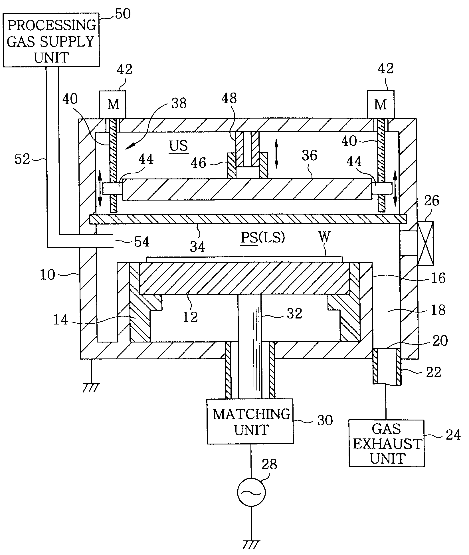
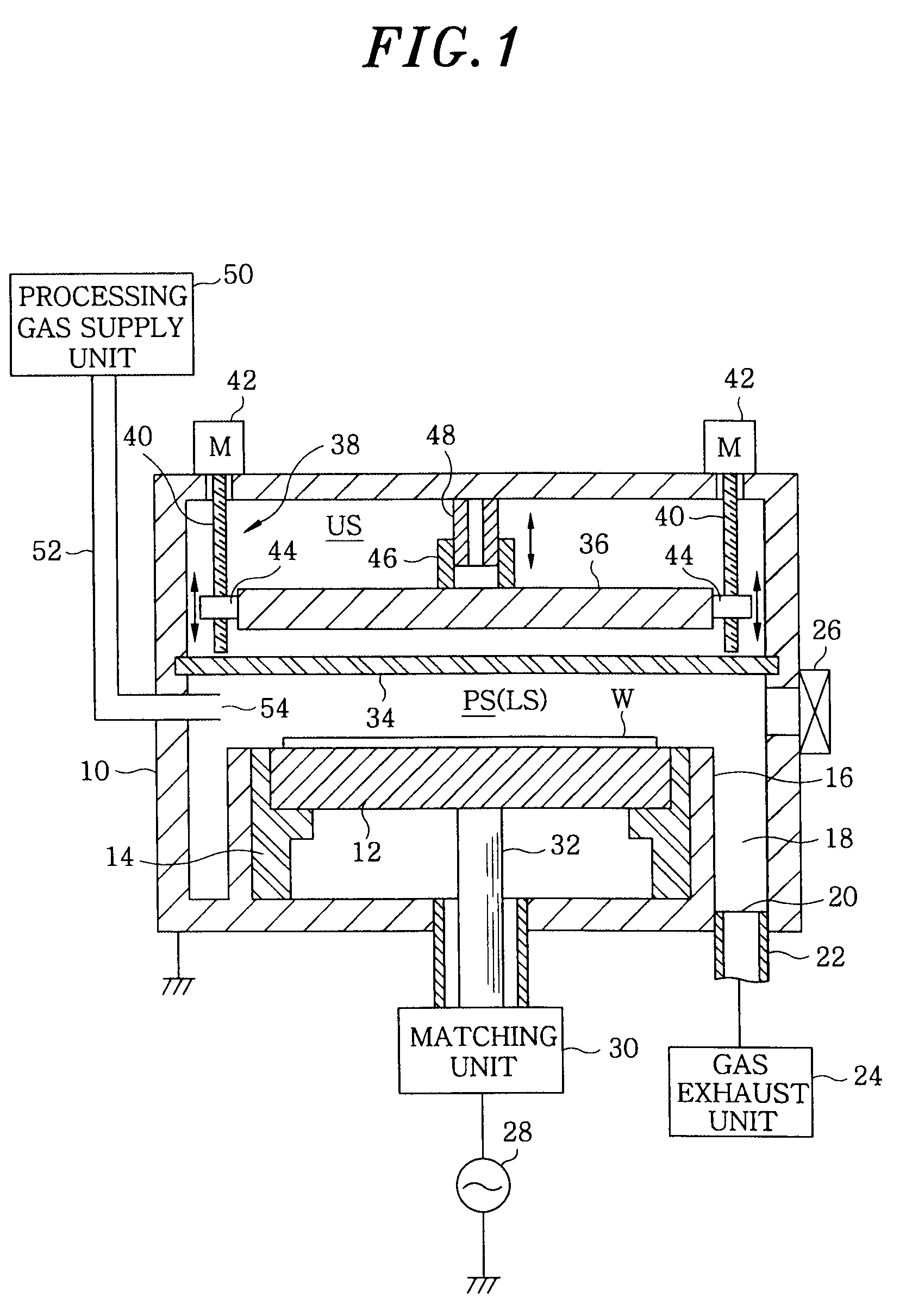
[0034]FIG. 1 shows a configuration of a plasma etching apparatus in accordance with the present invention. The plasma etching apparatus is configured as a capacitively coupled plasma etching apparatus of cathode coupled type having parallel plate electrodes, and includes a cylindrical chamber (processing vessel) 10 made of a metal such as aluminum, stainless steel or the like. The chamber 10 is frame grounded.

[0035]A circular plate-shaped susceptor 12 serving as a lower electrode for mounting thereon a substrate to be processed, e.g., a semiconductor wafer W, is disposed horizontally in the chamber 10. The susceptor 12 is made of, e.g., aluminum, and is supported by a cylindrical insulating supporting portion 14 which is made of ceramic and vertically extends from a bottom of the chamber 10 without being grounded. An annular gas exhaust path 18 is formed between the inner wall of the chamber 10 and a cylindrical conductive supporting portion 16 vertically extending from the bottom o...

third embodiment

[0061]FIG. 4 illustrates a configuration of a plasma processing apparatus in accordance with the present invention. This plasma processing apparatus is characterized by a configuration in which the upper electrode 36 is fixed at a specific position, and a position of the lower electrode 12 is vertically varied. Specifically, a circular plate-shaped lower electrode 12 is vertically movable in a cylindrical conductor cup 80 having a bottom portion which is coupled to the lower power feed rod 32, and a height position of the lower electrode 12 is varied by actuators 82 installed outside the chamber 10 via supporting rods 84. Here, the conductor cup 80 and the lower electrode 12 may be electrically connected to each other directly or via a flexible conductor (not shown). The supporting rods 84 may be formed of an insulator, and the actuators 82 may be formed as ball screw mechanisms, a cylinder or the like.

[0062]The top surface of the conductor cup 80 is airtightly sealed by a partition...

fourth embodiment

[0068]FIG. 5 describes a configuration of a plasma processing apparatus in accordance with the present invention. In this plasma processing apparatus, the susceptor (lower electrode) 12 and the upper electrode 36 facing each other in parallel are horizontally fixed at specific positions, and a cylindrical sidewall portion 100 made of, e.g., quartz, is provided on the sidewall of the chamber 10 facing the processing space PS formed between electrodes 12 and 36. Further, in addition to the quartz sidewall portion 100, a cylindrical side electrode 102 is disposed outside of the sidewall portion 100 to be movable or displaceable in a vertical direction.

[0069]To be more specific, a cathode coupled single frequency application type is employed in this plasma processing apparatus, so that the configuration around the susceptor (lower electrode) 12 may be the same as that described in the first embodiment (see FIG. 1). Meanwhile, the upper electrode 36 serves as the shower head 88 as well a...


PUM

PropertyMeasurementUnit
frequencyaaaaaaaaaa
dielectric constantaaaaaaaaaa
frequencyaaaaaaaaaa

Abstract

A plasma processing apparatus includes a processing chamber; a first electrode for mounting thereon a target substrate in the processing chamber; a second electrode which faces the first electrode obliquely or in parallel thereto to form a high frequency discharging capacitor; a processing gas supply unit for supplying a processing gas to a processing space in the processing chamber; a first high frequency power supply for applying a first high frequency power to at least one of the first and the second electrode to generate a plasma by injecting the processing gas into the processing space; and an electrode position varying mechanism for varying a position of the second electrode in a predetermined direction to vary a capacitance of the capacitor. The apparatus further includes a dielectric partition wall for separating the processing space from an electrode moving space surrounding the second electrode and the electrode position varying mechanism.

Description

FIELD OF THE INVENTION [0001]The present invention relates to a technique for performing plasma processing on a substrate to be processed; and, more particularly, to a capacitively coupled plasma processing apparatus.BACKGROUND OF THE INVENTION [0002]In a manufacturing process of a semiconductor device or an FPD (flat panel display), a plasma is often used in processes, e.g., etching, deposition, oxidation, sputtering and the like, in order to make a processing gas react efficiently at a relatively low temperature. Conventionally, a capacitively coupled plasma processing apparatus capable of generating a plasma of a large diameter is mainly used for a single-wafer plasma processing apparatus.[0003]Generally, in the capacitively coupled plasma processing apparatus, an upper and a lower electrode are disposed in parallel with each other in a processing chamber as a vacuum chamber, and a substrate to be processed (e.g., a semiconductor wafer, a glass substrate or the like) is mounted o...

Claims


Application Information

Patent Timeline
Patent Type & Authority Applications(United States)
IPC IPC(8): C23C16/513
CPCC23C16/5096H01J37/32623H01J37/32568H01J37/32091
Inventor YAMAZAWA, YOHEI
Owner TOKYO ELECTRON LTD
Why Eureka
Try Eureka