Membrane-electrode assembly, electrolytic cell employing the same, electrolytic-water sprayer, and method of sterilization

Inactive Publication Date: 2009-05-21
DE NORA PERMELEC LTD +1
View PDF6 Cites 73 Cited by
  • Summary
  • Abstract
  • Description
  • Claims
  • Application Information

AI Technical Summary

Benefits of technology

[0084](4) Novel composite electrolytic water (having a novel sterilizing effect brought about by adding an organic acid or surfactant for pH regulation for the purpose of improving bactericidal activity or by adding an alcohol or the like for the purpose of, e.g., improving bactericidal activity or refreshing feeling)
[0085]In the membrane-electrode assembly produced by disposing, in a

Problems solved by technology

(1) Although use of an ion-exchange membrane or the like improves ionic conductivity and this is expected to increase electrolysis reaction efficiency, it has been difficult to join the membrane or the like with the electrodes.
(2) The membrane usually is nonporous and is used usually in combination with porous electrodes for facilitating the feeling of an electrolytic solution

Method used


Image

  • Membrane-electrode assembly, electrolytic cell employing the same, electrolytic-water sprayer, and method of sterilization
  • Membrane-electrode assembly, electrolytic cell employing the same, electrolytic-water sprayer, and method of sterilization
  • Membrane-electrode assembly, electrolytic cell employing the same, electrolytic-water sprayer, and method of sterilization

Examples


example 1

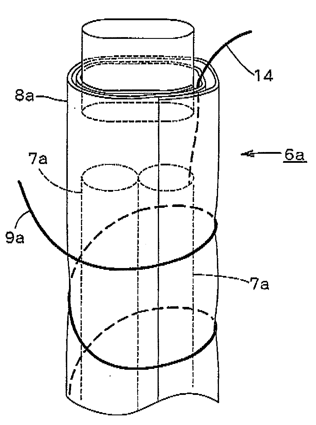
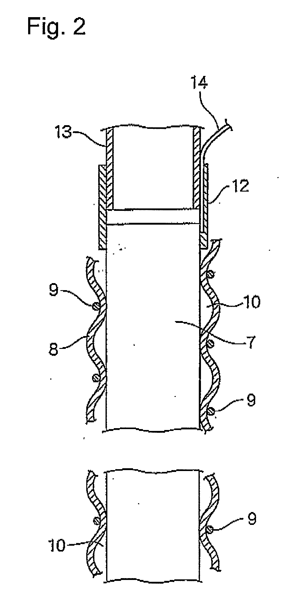
[0198]A rod made of niobium (diameter, 2 mm) on which a conductive-diamond catalyst (dopant boron concentration, 2,500 ppm) had been deposited was placed as an anode in a tubular ion-exchange membrane (Nafion 350, manufactured by DuPont; thickness, 0.35 mm; diameter, 3 mm). A commercial platinum wire (diameter, 0.4 mm) was spirally wound as a cathode on the diaphragm to obtain an anode-membrane-cathode assembly. The winding pitch was 4 mm. Tubes (diameter, 4 mm) were bonded to upper and lower parts of the assembly, and feeder wires from a DC power source were connected to the respective electrodes to obtain an electrolytic cell. Pure water was passed upward through the anode chamber at a rate of 40 cc / min. Currents of 0.5 A and 1 A were separately caused to flow. As a result, the cell voltages were 13 V and 19 V, respectively, the ozonized water concentrations were 8 ppm and 21 ppm, respectively, and the ozone generation efficiencies were 13% and 12%, respectively, in these operatio...

example 2

[0202]Those parts of the membrane in the assembly of Example 1 which constituted the two openings of the anode chamber were fixed to tubes having a diameter of 4 mm. The resultant member was disposed in a second tube having an inner diameter of 5 mm to form a cathode chamber between the second tube and the membrane. A feeder terminal for the wire cathode was connected to the cathode in the second tube. A 2 g / L aqueous solution of sodium chloride was fed to the anode chamber at a rate of 40 cc / min, and water was fed also to the cathode chamber in the same manner. A current of 1 A was caused to flow. As a result, alkaline water containing hydrogen and having a pH of 11 and acid water containing hypochlorite ions in an amount of 40 ppm could be simultaneously yielded.

example 3

[0203]The same test as in Example 2 was conducted, except that tap water was fed to the anode chamber and the cathode chamber. As a result, the ozonized water yielded at 0.5 A had a concentration of 4.5 ppm (current efficiency, 7.3%).


PUM

PropertyMeasurementUnit
Lengthaaaaaaaaaa

Abstract

The present invention provides a membrane-electrode assembly which comprises: at least one rod-form or tubular electrode; a tubular diaphragm disposed around the periphery of the electrode; and a wire-form counter electrode disposed around the periphery of the diaphragm, the diaphragm being fixed to the rod-form or tubular electrode with the wire-form counter electrode to thereby form an electrode chamber having a gas/liquid passage between the diaphragm and the rod-form or tubular electrode.

Description

FIELD OF THE INVENTION[0001]The present invention relates to a membrane-electrode assembly for yielding electrolytic water to be used for sterilization, cleaning, etc., an electrolytic cell employing the assembly, an electrolytic-water sprayer including any of the electrolytic cell, and a method of sterilization using these.BACKGROUND OF THE INVENTIONBactericide / Disinfectant Solution:[0002]Chlorine compound bactericides such as sodium hypochlorite, calcium hypochlorite, and sodium dichloroisocyanurate have been extensively used as bactericides / disinfectants in a wide range of environments. Of these, hypochlorites including sodium hypochlorite are in general use from the standpoints of cost and effect. However, many proposals have been made for attaining improvements in the bactericidal / disinfectant effect thereof which are required in various fields including the clinical field and the food industry (see, for example, JP-A-2001-253803, JP-A-2001-342496, and JP-A-2002-145710).[0003]U...

Claims


Application Information

Patent Timeline
IPC IPC(8): C25B1/00C25B11/02C25B9/10C25B9/19C25B9/23
CPCA61L2/0088C25B11/02A61L2/183A61L2/186A61L2202/11A61L2202/15C02F1/4618C02F1/66C02F2001/46142C02F2001/46152C02F2001/46161C02F2201/003C02F2201/4611C02F2201/46115C02F2201/46125C02F2201/46145C02F2301/026C02F2305/04C25B1/13C25B9/08A61L2/18C25B9/19
Inventor KITAORI, NORIYUKISEKIDO, KOTASHIBATA, TOMOYASUSUZUKI, TOMOHISATANAKA, MASASHIFURUTA, TSUNETONISHIKI, YOSHINORI
Owner DE NORA PERMELEC LTD
Why Eureka
Try Eureka