
Rare earth alloy binderless magnet and method for manufacture thereof

Active Publication Date: 2009-05-21
HITACHI METALS LTD +1
View PDF8 Cites 15 Cited by
  • Summary
  • Abstract
  • Description
  • Claims
  • Application Information

AI Technical Summary

Benefits of technology

[0020]In order to overcome the problems described above, the present invention has an object of providing a magnet that will achieve high size precision and show great flexibility in shape and yet exhibit higher thermal resistance and better magnetic properties than a bonded magnet.
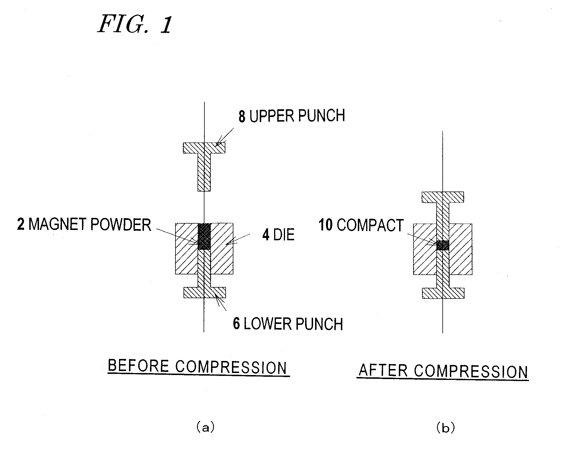
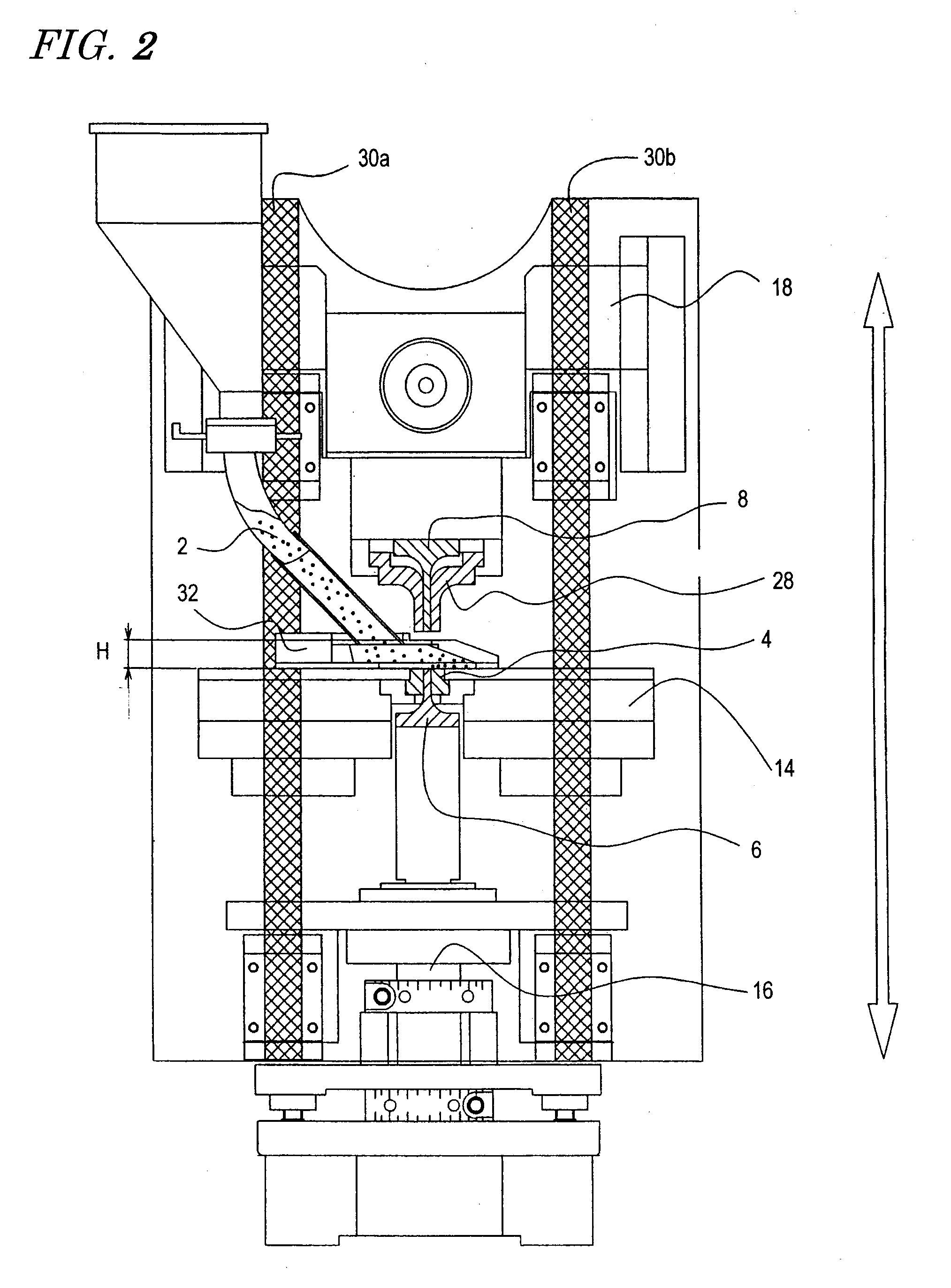
[0041]As used herein, the “compressed compact” means a powder compact obtained by compressing and compacting a magnetic powder of a rapidly solidified rare-earth alloy and / or a soft magnetic powder by a cold process. Also, the “binderless magnet” and “resin-less compressed powder magnetic core” refer herein to compacts in which powder particles are bound together without a resin binder by thermally treating a magnetic powder and a compressed compact of a soft magnetic powder, respectively. Furthermore, the “green compact” will refer herein to an aggregation of powder particles yet to be compressed and compacted by a cold process, irrespective of its density. A powder yet to be compressed and compacted by a cold process may assume the shape of such a green compact. According to the present invention, no resin binder is used, and the heat resistant temperature of the magnet is not restricted by that of any resin binder, thus achieving good thermal resistance. In addition, since there is no need to perform the process step of mixing and kneading a magnetic powder and a resin binder together, the manufacturing cost can be cut down, too.
[0042]Besides, according to the present invention, the magnet includes a higher volume fraction of magnetic powder than a bonded magnet, and therefore, achieves better magnetic properties than the bonded magnet. Consequently, even a small-sized magnet with a diameter of 4 mm or less, which would be hard to exhibit good enough magnetic properties if the magnet is a bonded magnet, can also exhibit excellent properties as a magnet according to the present invention.

Problems solved by technology

However, the thermal resistant temperature of such a bonded magnet is restricted by not only the thermal resistant temperature of the magnetic powder used but also that of the resin binder used to bind the magnetic powder.
Besides, since a bonded magnet includes an electrically insulating resin binder, it is difficult to carry out a surface treatment such as electrical plating or an evaporation and deposition process of a metal coating.
That is to say, the magnetic properties of conventional bonded magnets are not enough in those applications more and more often.
However, since the magnet is produced by a hot pressing technology such as a hot-press process, the press cycle is too long to achieve good mass productivity.
As a result, the manufacturing cost of the magnets will increase, thus making it difficult to mass-produce such magnets in practice.
This process also has too long a press cycle to achieve good mass productivity.
As can be seen, any of these conventional techniques for compacting a magnetic powder without using a resin binder achieves either just low mass productivity or a magnetic powder volume fraction that is essentially no different from that of a bonded magnet.
However, the green compact will shrink significantly during the sintering process.
That is to say, since the compact changes its shapes significantly after the press compaction process, the size precision and flexibility in shape of a sintered magnet are much inferior to those of a bonded magnet.

Method used


Image

  • Rare earth alloy binderless magnet and method for manufacture thereof
  • Rare earth alloy binderless magnet and method for manufacture thereof
  • Rare earth alloy binderless magnet and method for manufacture thereof

Examples


examples

[0113]First, as magnetic powders, provided were a rare-earth-iron-boron (R—Fe—B) based isotropic nanocomposite magnetic powders SPRAX-XB, -XC and -XD produced by Neomax Company, an R—Fe—B based magnetic powder including an Nd2Fe14B phase as a single magnetic phase (which will be identified herein by Ni) and R—Fe—B based isotropic nanocomposite magnetic powders including a hard magnetic Nd2Fe14B phase and a soft magnetic α-Fe phase (which will be identified herein by N2 and N3). The following Table 1 shows the alloy compositions of these six types of magnetic powders and Table 2 shows the magnetic properties and average particle sizes of the magnetic powders themselves:

TABLE 1MagneticAlloy composition (at %)powderNdPrFeCoBCTiMSPRAX-XB6.01.076.0—12.01.04.0—SPRAX-XC9.0—73.0—12.61.43.0Nb1.0SPRAX-XD8.0—71.04.011.01.05.0—N111.5—75.55.55.5——Zr2.0N29.0—76.08.05.50.51.0—N3—8.373.78.05.50.54.0—

TABLE 2RemanenceCoercivityMaximum energyAverageMagneticBrHcJproduct (BH)maxparticlepowder(mT)(kA / m)(...

example # 8

Example #8

[0126]A magnetic powder was made out of flakes of a rapidly solidified alloy (with an average thickness of 25 μm and) having the alloy composition N2 shown in Table 1 and a compressed compact was obtained as Example #8 with the same machine and by the same method as those adopted in Examples #1 and #4 through #7. The dimensions of the compressed compact included an inside diameter of 7.7 mm, an outside diameter of 12.8 mm and a height of mm. The following Table 6 shows the average thicknesses of flakes of the rapidly solidified alloys, the mean particle sizes of pulverized powders, compaction conditions, and the densities of binderless magnets after the compressed compacts were thermally treated for Examples #8 and #6:

TABLE 6Averagethickness(μm) ofMeanrapidlyparticlesolidifiedsizeCompactingMagnetMagneticalloy(μm) ofCompactionResinpressuredensitypowderflakepowdermethodbinder(MPa)(Mg / m3)Ex. 8N22590CompressionNO1,9006.7Ex. 6N28090CompressionNO1,9006.5

[0127]If the mean particl...


PUM

PropertyMeasurementUnit
Grain sizeaaaaaaaaaa
Temperatureaaaaaaaaaa

Abstract

A method for producing a rare-earth alloy based binderless magnet according to the present invention includes the steps of: (A) providing a rapidly solidified rare-earth alloy magnetic powder; and (B) compressing and compacting the rapidly solidified rare-earth alloy magnetic powder by a cold process without using a resin binder, thereby obtaining a compressed compact, 70 vol % to 95 vol % of which is the rapidly solidified rare-earth alloy magnetic powder.

Description

BACKGROUND OF THE INVENTION[0001]1. Field of the Invention[0002]The present invention relates to a rare-earth alloy based binderless magnet and a method for producing such a magnet. More particularly, the present invention relates to a magnet produced by compacting a powder of a rapidly solidified rare-earth magnetic alloy under an ultrahigh pressure.[0003]2. Description of the Related Art[0004]Bonded magnets, obtained by adding a resin binder to a magnetic powder of a rapidly solidified rare-earth alloy, achieve high size precision and show great flexibility in shape, and have been used extensively in various types of electronic devices and electric components. However, the thermal resistant temperature of such a bonded magnet is restricted by not only the thermal resistant temperature of the magnetic powder used but also that of the resin binder used to bind the magnetic powder. As for a compressed bonded magnet that uses a thermosetting epoxy resin, for example, the thermosetting...

Claims


Application Information

Patent Timeline
IPC IPC(8): H01F7/02B22F3/16
CPCB22F1/0044B22F2003/033H01F41/0266H01F1/058H01F1/0579H01F1/0576C22C2202/02C22C1/0441B22F2998/10B22F2998/00B22F2003/248B22F2003/145B22F3/02B22F2202/03B22F2202/06B22F3/03B22F3/004B22F9/008B22F3/24B22F1/07H01F1/08H01F7/00
Inventor KANEKIYO, HIROKAZUMIYOSHI, TOSHIOBEKKI, KATSUNORIUEMOTO, IKUOISHIKAWA, KAZUO
Owner HITACHI METALS LTD
Learn More