Optical Receiver For Receiving A Signal With M-Valued Quadrature Amplitude Modulation With Differential Phase Coding And Application Of Same

a technology of optical receiver and optical data, applied in electromagnetic receivers, electromagnetic transmission, multiple carrier systems, etc., can solve the problems of heterodyne reception disadvantages, high data rate, wdm and high data ra

Inactive Publication Date: 2009-05-21
FRAUNHOFER GESELLSCHAFT ZUR FOERDERUNG DER ANGEWANDTEN FORSCHUNG EV
View PDF8 Cites 35 Cited by
  • Summary
  • Abstract
  • Description
  • Claims
  • Application Information

AI Technical Summary

Benefits of technology

[0037]The electronic network for compensation of the phase noise in the phase diversity receiver according to the invention can be realized, in principle, with analog components or else with digital signal processing. In the case of homodyne reception, care should likewise be taken here to ensure corresponding frequencies of signal and local lasers. Deviations lead to a loss of performance. The frequency equality must therefore possibly be guaranteed by additional outlay. For this purpose it is possible to use for example an automatic frequency control loop (AFC loop) or else a digital estimation of the frequency deviation.
[0038]A further advantage of the receiver proposed by the invention is that the entire receiver structure through to the decision units, for the same symbol rate, has a construction independent of the modulation format. This makes the use of the receivers in adaptive systems conceivable, wherein different modulation formats can be realized by sole adaptation of the concluding decision unit electronics and also data reconstruction logic. Both the modular replacement of modulation-specific electronic modules and the parallel design for different modulation formats by means of arrays of electronic modules are conceivable.
[0039]Future investigations will show which modulation formats can be used particularly expediently in which network segments. The flexibility of the receiver proposed by the invention with regard to the modulation formats permits use in optical wide area, metropolitan and access networks.

Problems solved by technology

What proved to be difficult, on the other hand, in a coherent reception are the frequency synchronization of signal and local lasers (controllable for example by an automatic frequency control loop), the control of the polarization (handleable by the polarization diversity method) and also the phase noise.
Heterodyne reception has disadvantages, however, in WDM and at high data rates since the components required have to operate at very high frequencies.

Method used


Image

  • Optical Receiver For Receiving A Signal With M-Valued Quadrature Amplitude Modulation With Differential Phase Coding And Application Of Same
  • Optical Receiver For Receiving A Signal With M-Valued Quadrature Amplitude Modulation With Differential Phase Coding And Application Of Same
  • Optical Receiver For Receiving A Signal With M-Valued Quadrature Amplitude Modulation With Differential Phase Coding And Application Of Same

Examples


Embodiment Construction

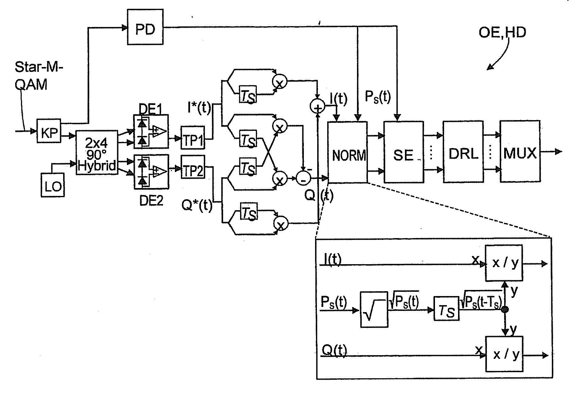
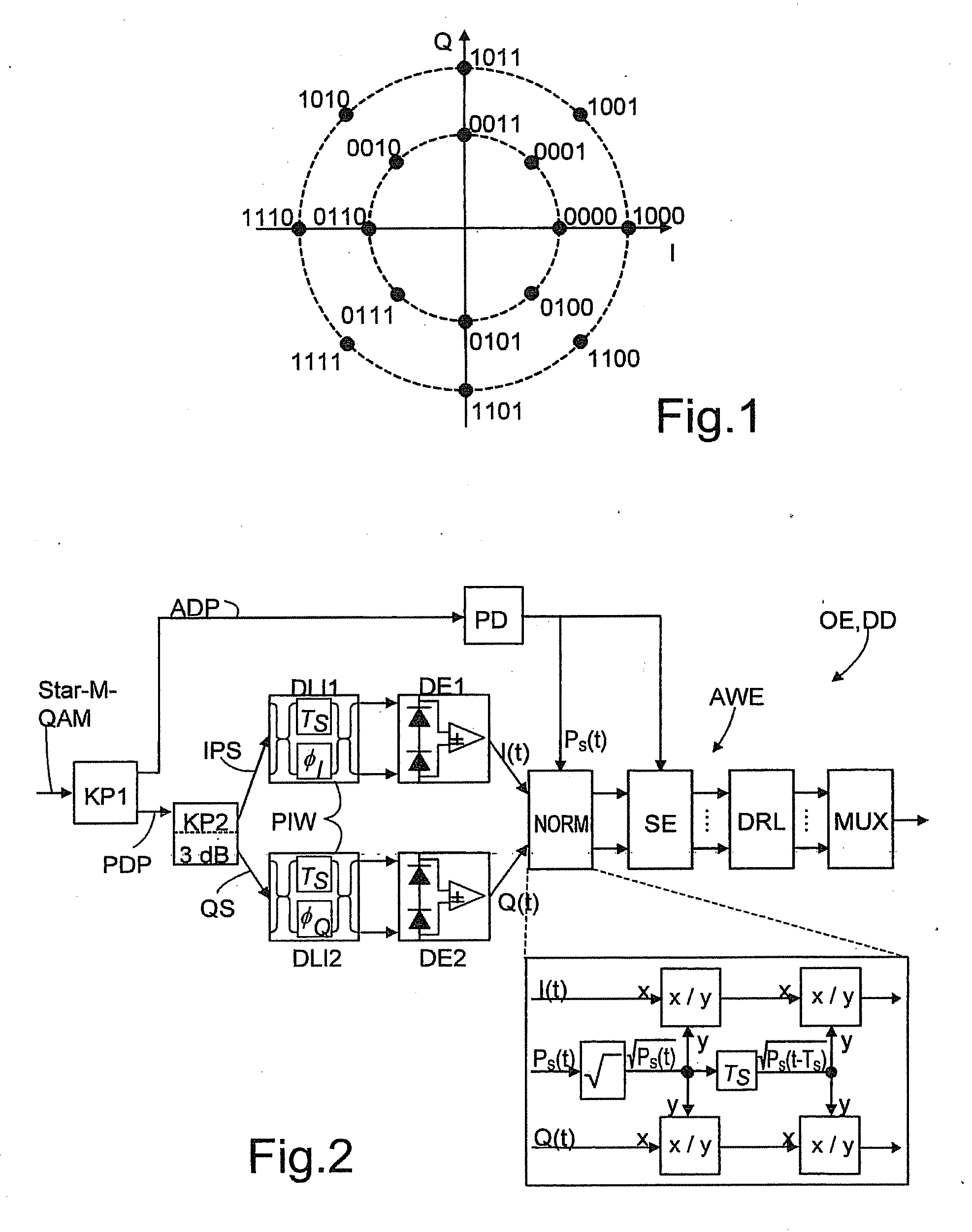
[0049]FIG. 1 shows a constellation diagram of a 16QAM with eight phase states. Data signals coded by such a higher-valued modulation method (M=number of symbols=8) can readily be received and decoded without any problems for the first time by means of the optical receiver according to the invention.

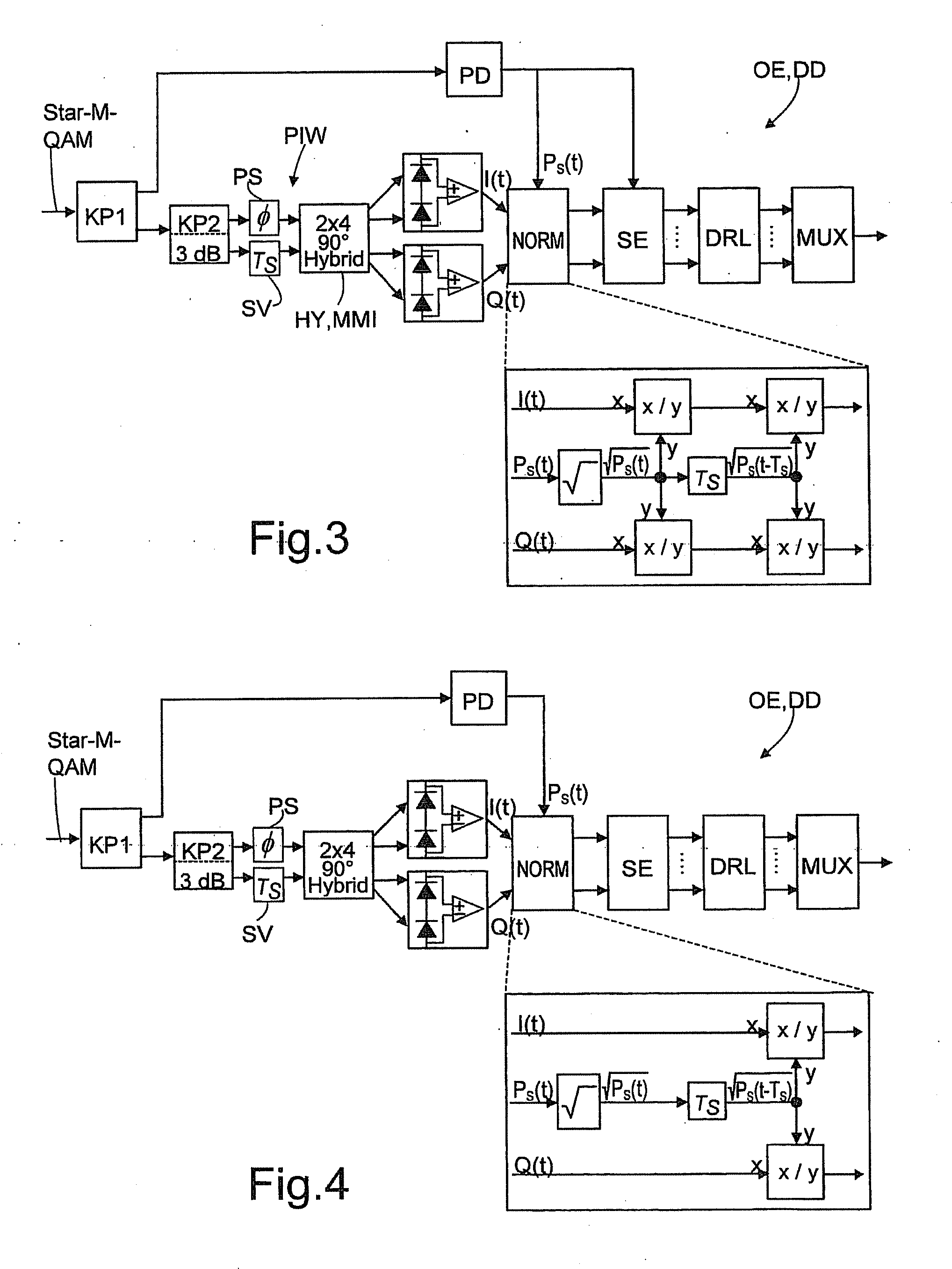
[0050]FIG. 2 shows the optical receiver OE according to the invention in the embodiment of an optical direct receiver DD. The received data signal Star-M QAM is split between an amplitude detection path ADP and a phase detection path PDP by means of a first optical coupler KP1. The amplitude detection path ADP contains a photodiode PD, which detects the incoming optical data signal and converts the amplitude or intensity thereof into a corresponding electric current. Arranged in the phase detection path PDP is a second optical coupler KP2 (with a uniform 3 dB signal splitting in the exemplary embodiment shown), which splits the received data signal between an in-phase signal path IPS and ...


PUM


Abstract

Optical data signal receiver having an optical separation of the received data signal into two signal paths, namely, an amplitude detection path and a phase detection path, wherein the phase detection path is split into an in-phase signal path generating in-phase-signals and a quadrature-signal path generating quadrature-signals, and both the in-phase-signal path and the quadrature-signal path, as well as the amplitude detection path, are connected to an analysis unit for demodulation of the received data signal, in which a normalizer and thereafter a symbol discriminator and a data reconstruction logic are arranged in the analysis unit. In the receiver, a connection is provided at least from the amplitude detection path to the normalizer, the normalizer normalizing the in-phase and quadrature-signals with the aid of the signal output from the amplitude detection path, the symbol discriminator discriminating the symbols output from the normalized in-phase and quadrature-signals. Additional connections can be provided from the amplitude detection path signal.

Description

CROSS-REFERENCE TO RELATED APPLICATION[0001]This application is a continuation of application PCT / EP2007 / 005549 filed 23 Jun. 2007.BACKGROUND[0002]The invention relates to an optical receiver for receiving an optical data signal which, through application of M-valued quadrature amplitude modulation (QAM) with differential phase coding, comprises individual symbols having the length of the symbol duration and contains an item of amplitude information and an item of differential phase information, comprising an optical splitting of the received data signal between two signal paths, of which one is embodied as an amplitude detection path and the other is embodied as a phase detection path, wherein the phase detection path is split into an in-phase signal path for generating in-phase signals and a quadrature signal path for generating quadrature signals, and in-phase signal path and quadrature signal path and also amplitude detection path are connected to an evaluation unit for the demo...

Claims


Application Information

Patent Timeline
Patent Type & Authority Applications(United States)
IPC IPC(8): H04B10/06H04B10/60H04B10/61H04B10/63H04B10/67
CPCH04B10/60H04B10/613H04L27/389H04B10/67H04L27/38H04B10/63
Inventor SEIMETZ, MATTHIAS
Owner FRAUNHOFER GESELLSCHAFT ZUR FOERDERUNG DER ANGEWANDTEN FORSCHUNG EV
Why Eureka
Try Eureka