Blasting method and blasting machine

a blasting machine and blasting method technology, applied in the direction of grinding machine components, grinding/polishing apparatus, manufacturing tools, etc., can solve the problems of inability to use applications or materials, forming a satin-like finish, and reducing the viscosity and elasticity of the carrier, so as to achieve low adhesiveness, maintain cutting force, and easy control of liquid volume to be merged

Active Publication Date: 2009-05-21
FUJI MFG CO LTD
View PDF1 Cites 16 Cited by
  • Summary
  • Abstract
  • Description
  • Claims
  • Application Information

AI Technical Summary

Benefits of technology

[0080]In addition, since the spray amount is changed based on a change in electrical-current value of the electrical-current detecting means 17, the volume of liquid to be merged can easily be controlled automatically.
[0081]When a gelatinous abrasive obtained by adding a coagulant to the kneaded material of devil's tongue powders, abrasive grains, and water is to be used for the elastic abrasive, only a small amount of abrasive grains falls out even when liquid (water) evaporates. In addition, even though abrasive grains exposed on the surface fall out, the gelatinous part is worn away and internally dispersed abrasive grains are newly exposed, thereby maintaining the cutting force. Furthermore, due to the relatively low adhesiveness, abrasive powders or burrs do not easily carry on and a change in the cutting force arising from the type of carrying is not easily induced. This ensures a blasting method for processing with stable accuracy.

Problems solved by technology

On the other hand, blasting has a disadvantage in that it processes the surface of a workpiece to a satin-like finish if a general abrasive is used, and therefore, it cannot be employed for applications or materials in which the formation of a satin-like finish is not desired.
However, heat generated during polishing causes water in the carrier to evaporate, thereby decreasing the viscosity and elasticity of the carrier.
Furthermore, although optimal polishing is ensured while water is retained in the abrasive, water evaporation cannot be completely prevented because the abrasive is continuously used.
More specifically, the elastic abrasive exhibits desired elasticity when a sufficient volume of water is contained, but becomes harder and more brittle as the water content decreases.
As described above, when water evaporates from the elastic abrasive and the hardness of the elastic abrasive is increased, it becomes more difficult for the abrasive to slide on the surface of the workpiece, or the abrasive bounces off, rather than sliding on the workpiece surface.
It causes the surface of the workpiece to become a satin-like finish, which greatly affects the glossiness and the workability of the surface of the processed workpiece.
In the case, the elastic abrasive becomes more brittle and the recovery rate of the abrasive decreases.
Thus, water sprayed from above onto this solidified abrasive cannot satisfactorily reach the lower layers of the abrasive though such water may reach the upper layers of the abrasive.
What is worse, if a large volume of water is supplied to sufficiently replenish the lower layers of the abrasive with water, the upper layers of the abrasive will be saturated with water.
If such abrasive saturated with water is ejected onto a workpiece, the workpiece will be contaminated with water adhering to it.
In addition, for blasting machines in which the abrasive is ejected together with a compressed gas, the abrasive in the form of particles aggregated due to water, resulting in relatively large secondary particles, will cause clogging in a blasting gun for ejecting the abrasive.
Furthermore, since the abrasive is ejected onto the workpiece in a state where flexible, a highly elastic abrasive replenished with a sufficient volume of water is mixed with dry, hard, and a brittle abrasive failing to absorb a sufficient volume of water, each component of the abrasive is bombarded on the workpiece surface in different states.
Thereby, an expected processing state cannot be achieved, and therefore, the quality of processed products decreases and the defective fraction increases.
Not only is the work extremely complicated but also machine operation needs to be suspended during the measurement.
However, in the method disclosed in the above-described '359 application, there is no way for acquiring data required for water volume adjustment during blasting.
In other words, an excessive or insufficient volume of water may be supplied, which increases the defective fraction.
Consequently, when the adhesive force is lost due to drying, some abrasive grains fall out, and therefore, the cutting force decreases.
Furthermore, even in a state where a sufficient volume of water is contained, once the abrasive carried on the surfaces falls out, the cutting force cannot be recovered.
Moreover, when burrs or cut powders generated during processing adhere to the abrasive surface by the adhesive force of the carriers, they add to the cutting force of the abrasive grains.
For the reason, the surface of the workpiece may be cut more than expected, failing to produce a mirror-like finish, in other words, failing to process the workpiece to have a desired surface.

Method used


Image

  • Blasting method and blasting machine
  • Blasting method and blasting machine
  • Blasting method and blasting machine

Examples


Embodiment Construction

[0090]Embodiments according to the present invention will now be described with reference to the attached drawings.

Overall structure of a blasting machine

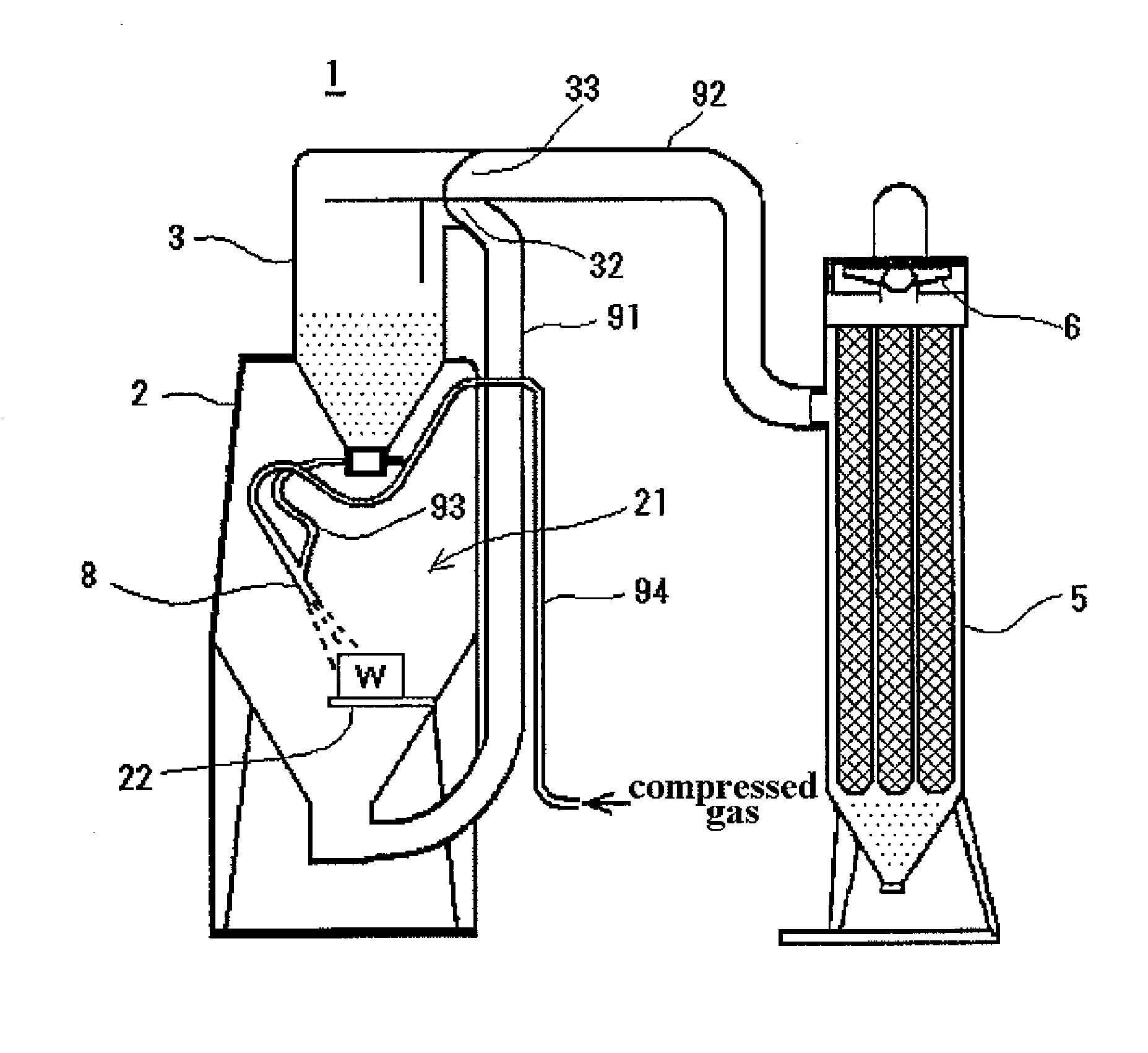
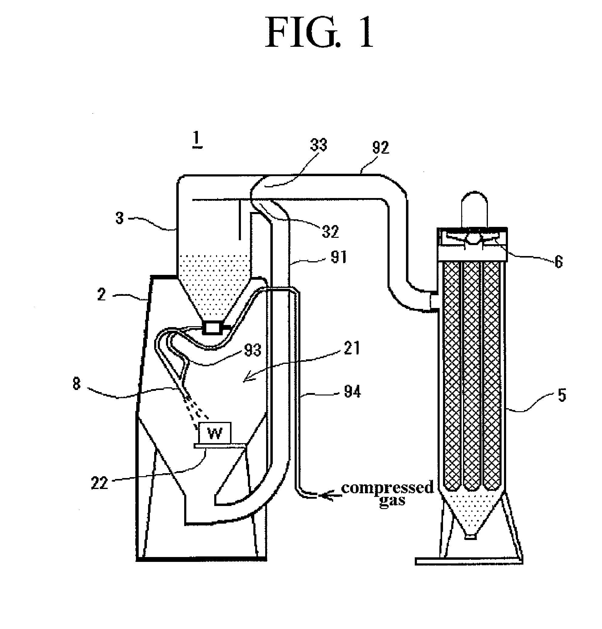
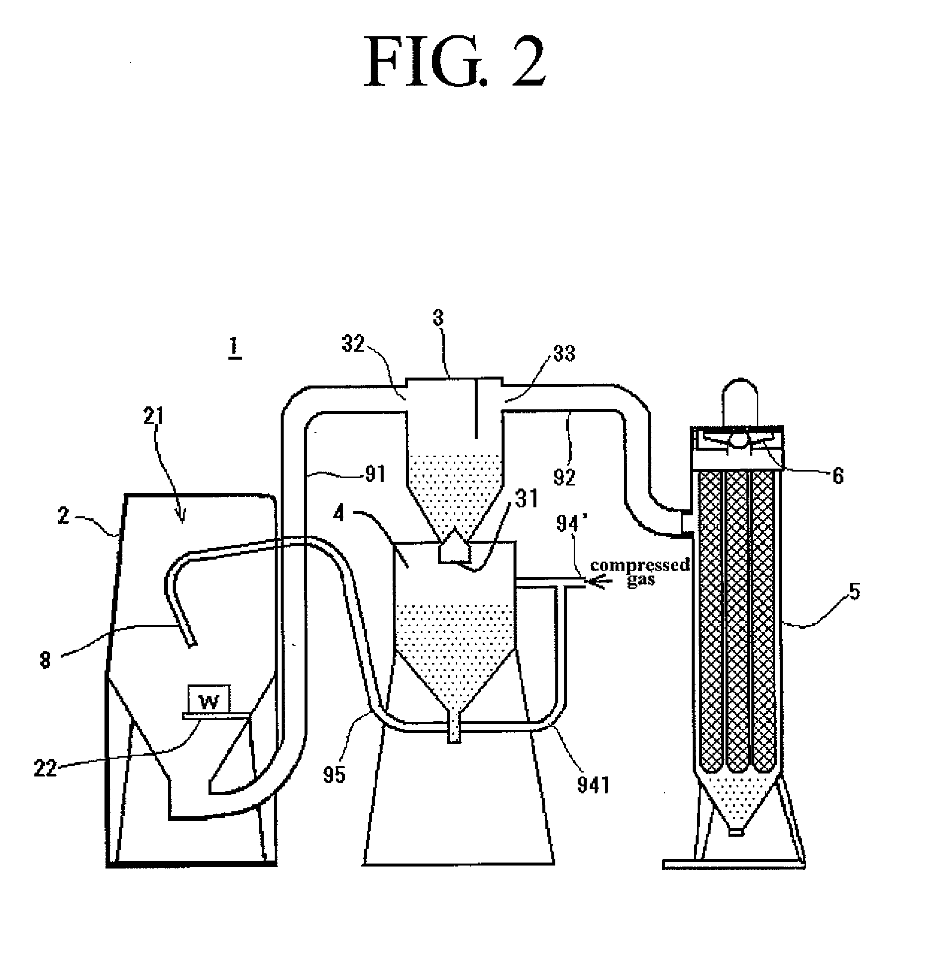
[0091]The overall structure of a blasting machine used for a blasting method according to the present invention will be described with reference to FIGS. 1 and 2.

[0092]A blasting machine 1 shown in FIG. 1 is a so-called “suction-type” blasting machine which includes an abrasive-supplying conduit 93 communicating with an abrasive-recovery tank 3 and a compressed-gas supply conduit 94 communicating with a compressed-gas supply source (not shown) such that the abrasive-supplying conduit 93 is combined with the compressed-gas supply conduit 94 in a blasting gun 8. With the help of negative pressure in the abrasive-supplying conduit 93 generated by a compressed gas, such as air, argon, or nitrogen (compressed air in the embodiment) introduced through the compressed-gas supply conduit 94, the abrasive from the abrasive-recovery tank 3 is...


PUM

PropertyMeasurementUnit
diameteraaaaaaaaaa
mean diameteraaaaaaaaaa
grain sizeaaaaaaaaaa

Abstract

In blasting with an abrasive containing liquid to confer elasticity, the abrasive from which liquid evaporates in the course of continuance use is uniformly supplied with liquid. Liquid for swelling an elastic abrasive is sprayed in an air flow for transporting the abrasive in a blasting machine 1 including an abrasive-recovery duct 91 communicating between a bottom of a cabinet 2 and an abrasive-recovery tank 3, the abrasive-recovery tank 3, a compressed gas before being introduced into a blasting gun 8, and so forth. Since the abrasive being transported in the air flow is separated into individual particles, each abrasive can be uniformly supplied with liquid.

Description

BACKGROUND OF THE INVENTION[0001]1. Field of the Invention[0002]The present invention relates to a blasting method and a blasting machine used for the blasting method and, more particularly, to a blasting method and a blasting machine in which an abrasive containing a certain amount of water or other liquid is used to confer desired elasticity (such abrasive is referred to as “elastic abrasive” in the specification).[0003]2. Description of the Related Art[0004]Compared with polishing using an abrasive paper, an abrasive cloth, a grindstone or the like, blasting in which an abrasive is ejected onto the surface of a workpiece along with a compressed gas, such as compressed air, can be applied relatively easily to an intricately shaped object. Therefore, blasting is widely used for various purposes, including cleaning of mold surfaces, removal of oxide films, and deburring of various products.[0005]For such blasting, sands or abrasive grains are generally used as the abrasive. Therefor...

Claims


Application Information

Patent Timeline
Patent Type & Authority Applications(United States)
IPC IPC(8): B24C1/00B24C9/00
CPCB24C1/083B24C1/086B24C9/006B24C9/003B24C7/00Y02P70/10B24C7/0015B24C9/00
Inventor MASE, KEIJIISHIBASHI, SHOZO
Owner FUJI MFG CO LTD
Why Eureka
Try Eureka