
Differential gear unit for motor vehicles comprising an active control mechanism for the driving force distribution

a technology of driving force and gear unit, which is applied in the direction of differential gearings, vehicle components, transmission elements, etc., can solve the problems of large use value limitation, large construction width, and inability to operate friction clutches with slippage for a relatively long time, so as to reduce construction space and wear, absorb very high forces, and withstand long-term operation

Inactive Publication Date: 2009-05-21
MAGNA STEYR FAHRZEUGTECHN
View PDF9 Cites 4 Cited by
  • Summary
  • Abstract
  • Description
  • Claims
  • Application Information

AI Technical Summary

Benefits of technology

[0005]It is therefore an object of the invention to develop a differential gear unit of the generic type in such a way that it can absorb very high forces and also withstands long-term operation with slip with very low installation space and wear.
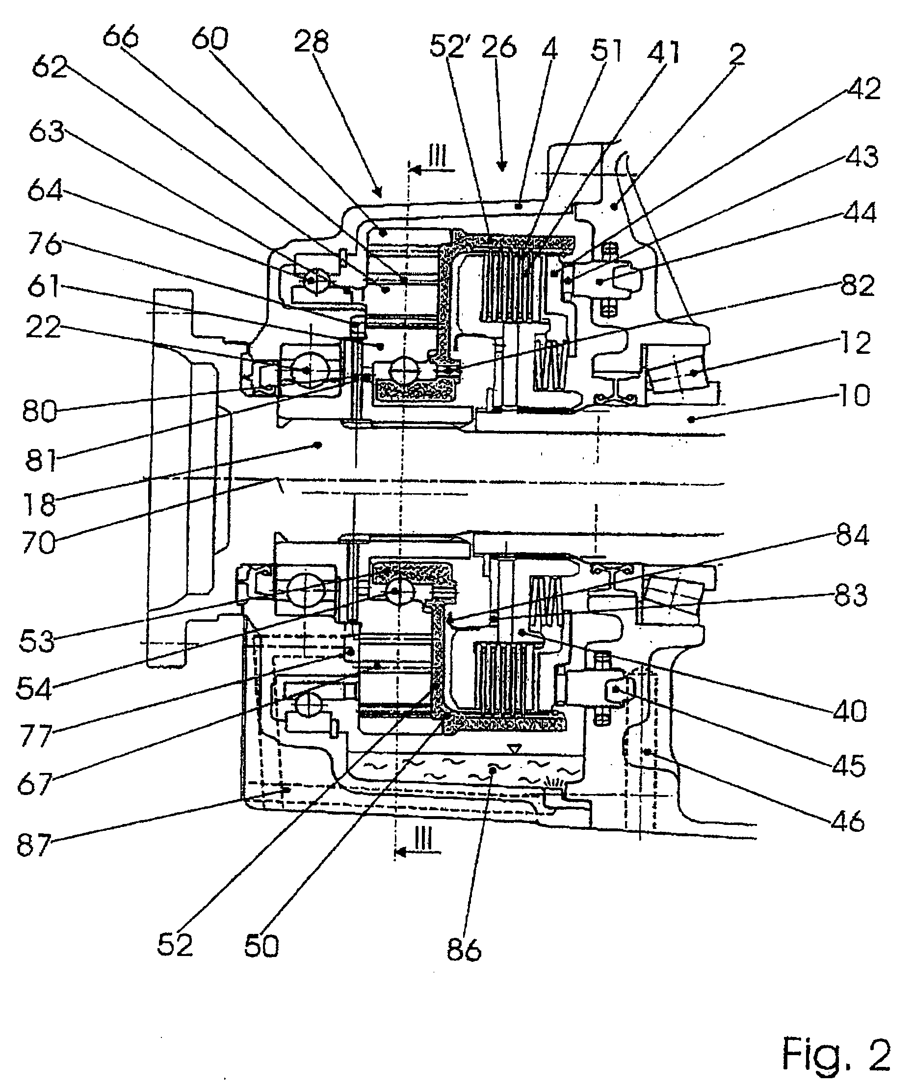
[0008]This gear mechanism design allows the transmission ratios which are favorable for this purpose to be realized in a very small space, for geometrical reasons and because internal toothing systems result in very high degrees of overlap (a large number of teeth are in engagement at the same time, over which the forces which are to be transmitted are distributed). The high degree of overlap also permits a particularly narrow and therefore space-saving configuration of the toothed elements. The transmission ratios which are possible with this permit an optimum design of the friction clutch for the corresponding differences in rotational speed, which contributes to the protection of said friction clutch and, in conjunction with satisfactory lubrication / cooling, makes said friction clutch particularly suitable for long-term slip operation.
[0009]In one development of the invention, the friction clutches comprising in each case a primary part which carries inner disks and a secondary part (the outer part) which carries outer disks, the secondary part of the clutch is combined structurally with the first element of the respective coaxial gear mechanism. Simple and narrow assemblies are therefore produced which are identical for both sides and can also be adapted and used easily for different transmission ratios in a modular design. Particularly favorable conditions for the mounting of the rotating parts are also provided by the combination of both components and the small extent in the axial direction.
[0010]This is particularly true if the secondary part of the clutch forms a bell, the respective coaxial gear mechanism adjoining the axially normal part of said bell, and the annular gear having a collar on its side (the outer side) which faces away from the clutch, which collar is mounted in the housing. The annular gear is therefore a particularly simple part and is mounted precisely and fixedly in the housing. Further space is saved and further costs are reduced by the fact that the collar of the annular gear is itself a bearing ring of a roller bearing.
[0011]In one particularly advantageous development of the invention, the coaxial gear mechanisms (28, 29) are configured with their adjacent wall parts as gearwheel oil pumps. Therefore, in addition to its gear mechanism function, the coaxial gear mechanism also acts as an oil pump. For this purpose, the crescent-shaped recesses in the adjacent walls which are known from gerotor pumps can be provided. In one special embodiment, the coaxial gear mechanisms have a crescent-shaped block between the first and / or second element and the annular gear, and two openings are provided in an adjacent housing part, from which two openings oil channels lead away, a first channel for the supply of oil from an oil sump and a second channel which produces a connection to the respective clutch directly or indirectly. The conveying action of the annular gear is increased considerably in this way. As a result of this and the pump action, large amounts of lubricating / cooling oil can be conveyed to the respective friction clutch, which ensures its long-term operation under slip, even with a further increase in loading.

Problems solved by technology

This type of construction requires a considerable installation width, which is unfavorable, however, in particular if homokinetic joints adjoin the axle shafts.
Furthermore, a differential gear unit of this type comprises a very large number of components which are difficult to mount and are loaded highly, and the lubrication / cooling of the clutch which is accommodated deep in the interior of the housing is critical.
In the case of insufficient cooling, the friction clutch cannot be operated with slip for a relatively long time.
Its use value is therefore greatly limited.

Method used


Image

  • Differential gear unit for motor vehicles comprising an active control mechanism for the driving force distribution
  • Differential gear unit for motor vehicles comprising an active control mechanism for the driving force distribution
  • Differential gear unit for motor vehicles comprising an active control mechanism for the driving force distribution

Examples


Embodiment Construction

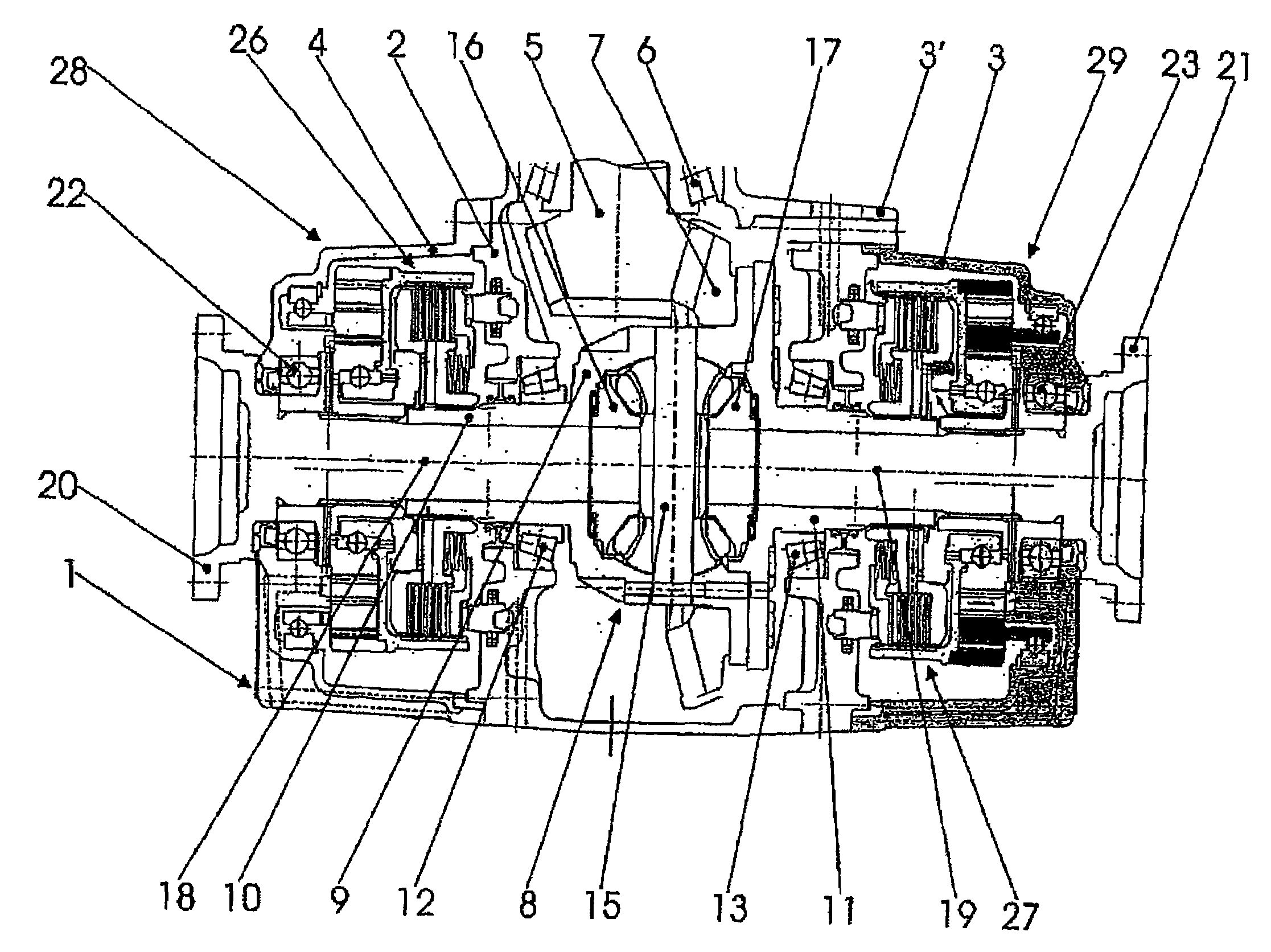
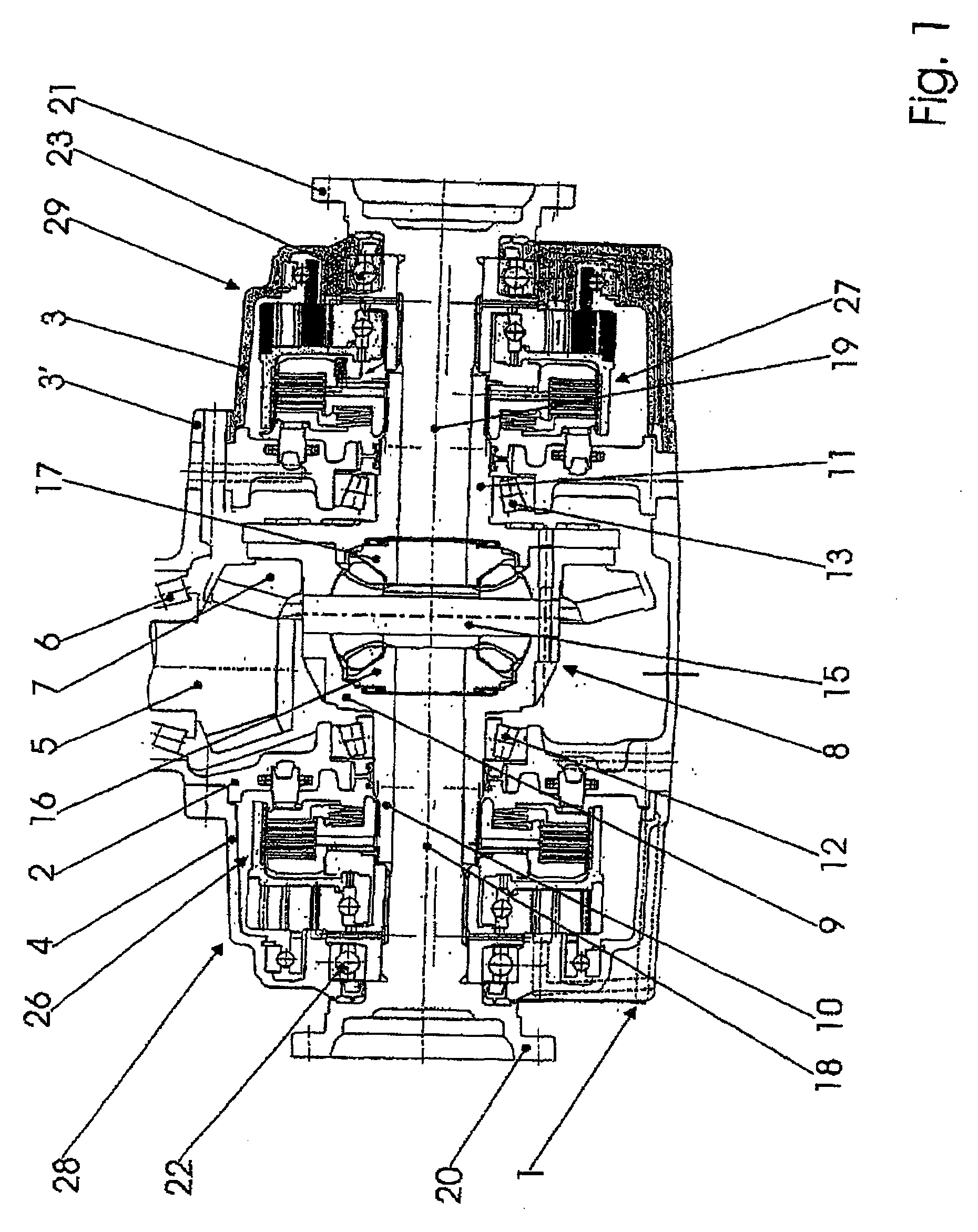
[0017]In FIG. 1, the housing of the differential gear unit according to the invention is denoted overall by 1. It comprises a center housing 2 and a right-hand and left-hand side housing 3, 4 which are screwed to the center housing 2 by way of a flange (such as, for example, 3′). The center housing 2 comprises a drive pinion 5, the one bearing 6 of which is indicated, a ring gear 7 which meshes with the drive pinion 5 and a differential which is connected fixedly in terms of rotation to the ring gear 7 and is denoted overall by 8.

[0018]As is customary, the differential 8 comprises a differential cage 9, a differential bolt 15 therein having differential bevel gears which are mounted on it, and a left-hand and a right-hand output bevel gear 16, 17. The differential cage 9 merges on both sides into a left-hand and a right-hand hollow shaft 10, 11 which are mounted in bearings 12, 13 in the center housing 2. The differential cage 9 with its two hollow shafts 10, 11 forms the driven ele...


PUM


Abstract

A differential gear unit for motor vehicles comprises a housing and, therein, a differential gear mechanism, two coaxial gear mechanisms and two controllable friction clutches, the coaxial gear mechanisms transmitting an additional torque to one or other axle shaft according to the degree of engagement of the friction clutches. In order for it also to be possible for very high forces to be absorbed in long-term operation with very low installation space and wear, the coaxial gear mechanisms have in each case one internal gear which is connected fixedly in terms of rotation to one side of the associated friction clutch, and one sun gear which is connected fixedly in terms of rotation to the respective output element, and the second element of each coaxial gear mechanism is a sun gear, and a third element is configured as an annular gear which has an external toothing system which meshes with the first element and an internal toothing system which meshes with the second element.

Description

BACKGROUND OF THE INVENTION[0001]The invention relates to a differential gear unit for motor vehicles, comprising a housing and, therein, a differential gear mechanism, two coaxial gear mechanisms and two controllable friction clutches, the differential gear mechanism comprising an element which can be driven (for example, a differential cage) and a first and second output element, for example the axle shafts, the coaxial gear mechanisms transmitting an additional torque to the first and second output elements according to the position of the friction clutches.[0002]Units of this type permit active motive power distribution control between the two output elements. The coaxial gear mechanism brings about a step-up or a step-down transmission ratio, with the result that the additional motive power can be metered via the controllable friction clutch to the respective output elements depending on the driving situation. Experts call this “torque vectoring”.[0003]A differential gear unit ...

Claims


Application Information

Patent Timeline
Patent Type & Authority Applications(United States)
IPC IPC(8): F16H48/22F16H48/06F16H57/04F04C2/10F16H37/08F16H48/08F16H48/30F16H48/32F16H48/34F16H48/40
CPCB60K17/20F04C2/101F04C2/102F16H48/08F16H48/22Y10T74/19F16H48/32F16H48/34F16H48/40F16H57/04F16H2200/2071F16H48/30
Inventor KASSLER, HELMUT
Owner MAGNA STEYR FAHRZEUGTECHN
Learn More