
System and Method for a Variable Home Position Dispense System

a technology of variable home position and dispense system, which is applied in the direction of positive displacement liquid engine, pump parameter, instrument, etc., can solve the problems of chemical waste exacerbated, extra chemical waste generated, and the hold-up volume also generates waste, so as to reduce the stagnation of process fluid, reduce the waste of unused process fluid, and reduce the hold-up volume of the pump

Active Publication Date: 2009-05-21
ENTEGRIS INC
View PDF99 Cites 42 Cited by
  • Summary
  • Abstract
  • Description
  • Claims
  • Application Information

AI Technical Summary

Benefits of technology

[0009]Embodiments of the present invention provide a system and method of fluid pumping that eliminates, or at least substantially reduces, the shortcomings of prior art pumping systems and methods. One embodiment of the present invention can include a pumping system comprising a dispense pump having a dispense diaphragm movable in a dispense chamber, and a pump controller coupled to the dispense pump. The pump controller, according to one embodiment, is operable to control the dispense pump to move the dispense diaphragm in the dispense chamber to reach a dispense pump home position to partially fill the dispense pump. The available volume corresponding to the dispense pump home position is less than the maximum available volume of the dispense pump and is the greatest available volume for the dispense pump in a dispense cycle. The dispense pump home position is selected based on one or more parameters for a dispense operation.

Problems solved by technology

One issue is that extra chemical waste is generated When the dispense system is initially primed, excess fluid than what is used for the dispense operations is required to fill the extra volume at the dispense pump and / or feed pump.
The hold-up volume also generates waste when flushing out the dispense system.
The problem of chemical waste is exacerbated as hold-up volume increases.
A second issue with a hold-up volume is that fluid stagnation takes place.
Again, these problems are made worse with a larger hold-up volume especially in low dispense volume applications.
Stagnation of fluid can have deleterious effect on a dispense operation.
Because many semiconductor manufacturing process chemicals are expensive (e.g., thousands of dollars a liter), new chemicals are tested on wafers in small batches.
This is an inaccurate, time consuming and potentially dangerous process that is not representative of the actual dispense process.

Method used


Image

  • System and Method for a Variable Home Position Dispense System
  • System and Method for a Variable Home Position Dispense System
  • System and Method for a Variable Home Position Dispense System

Examples


Embodiment Construction

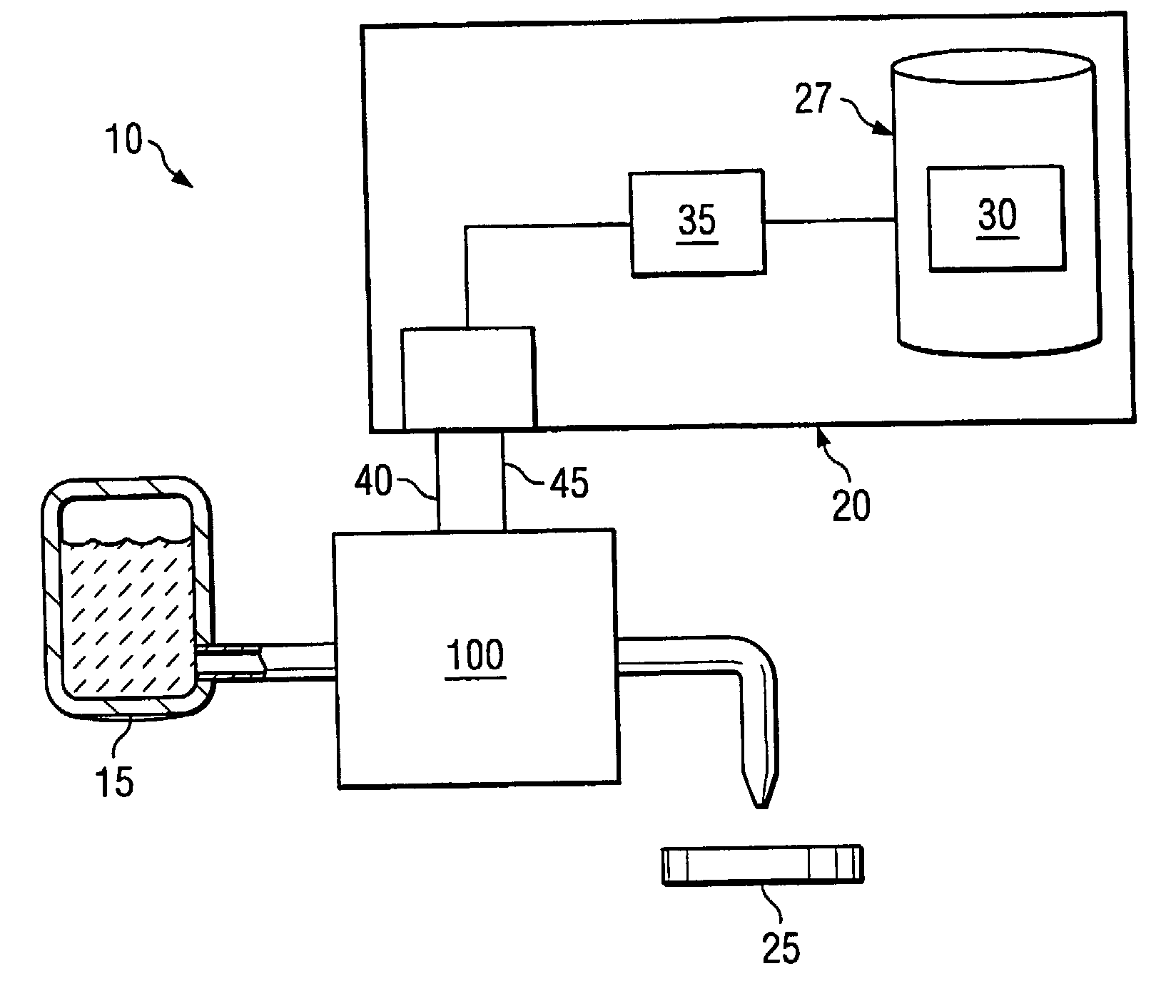
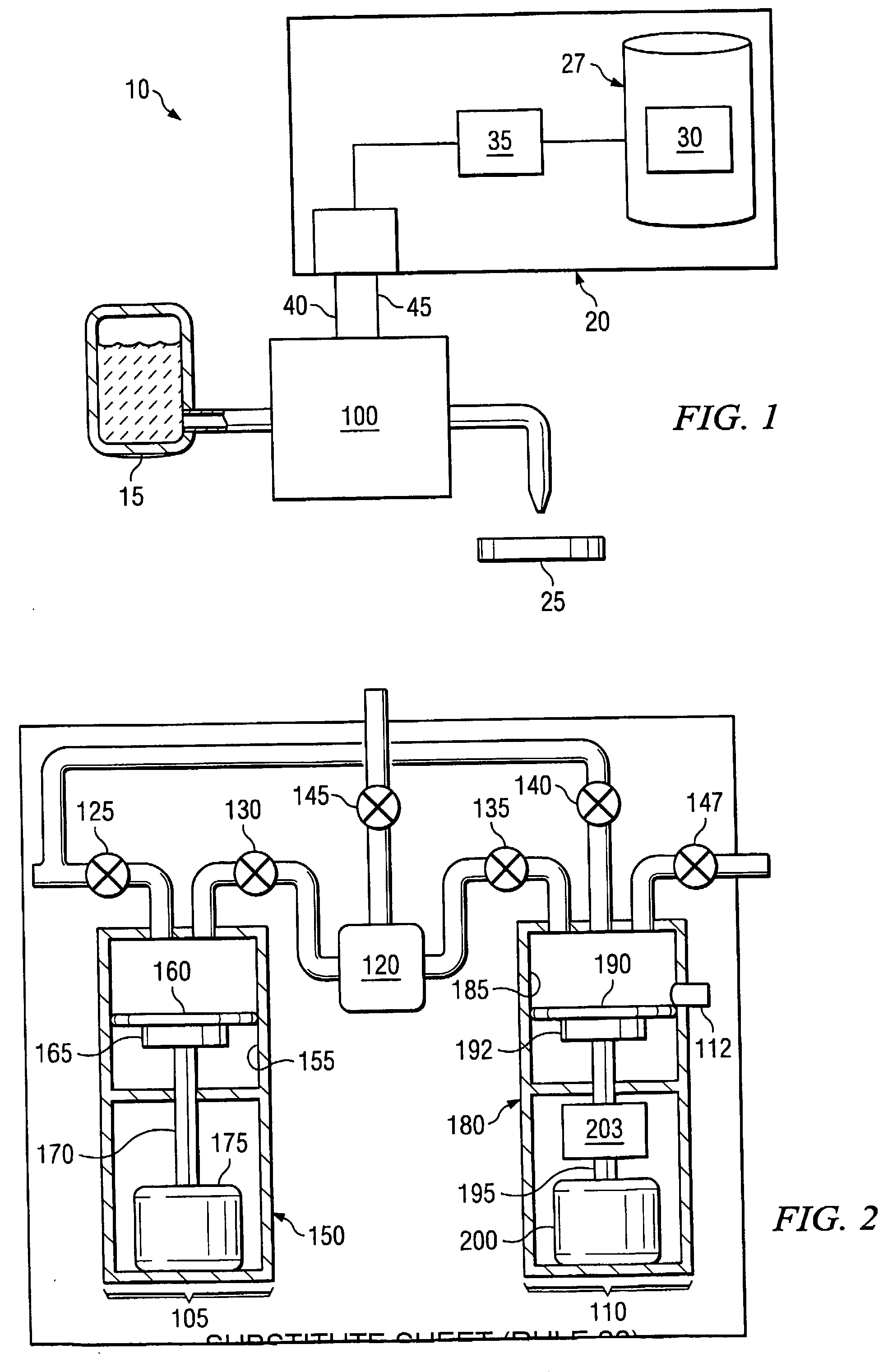
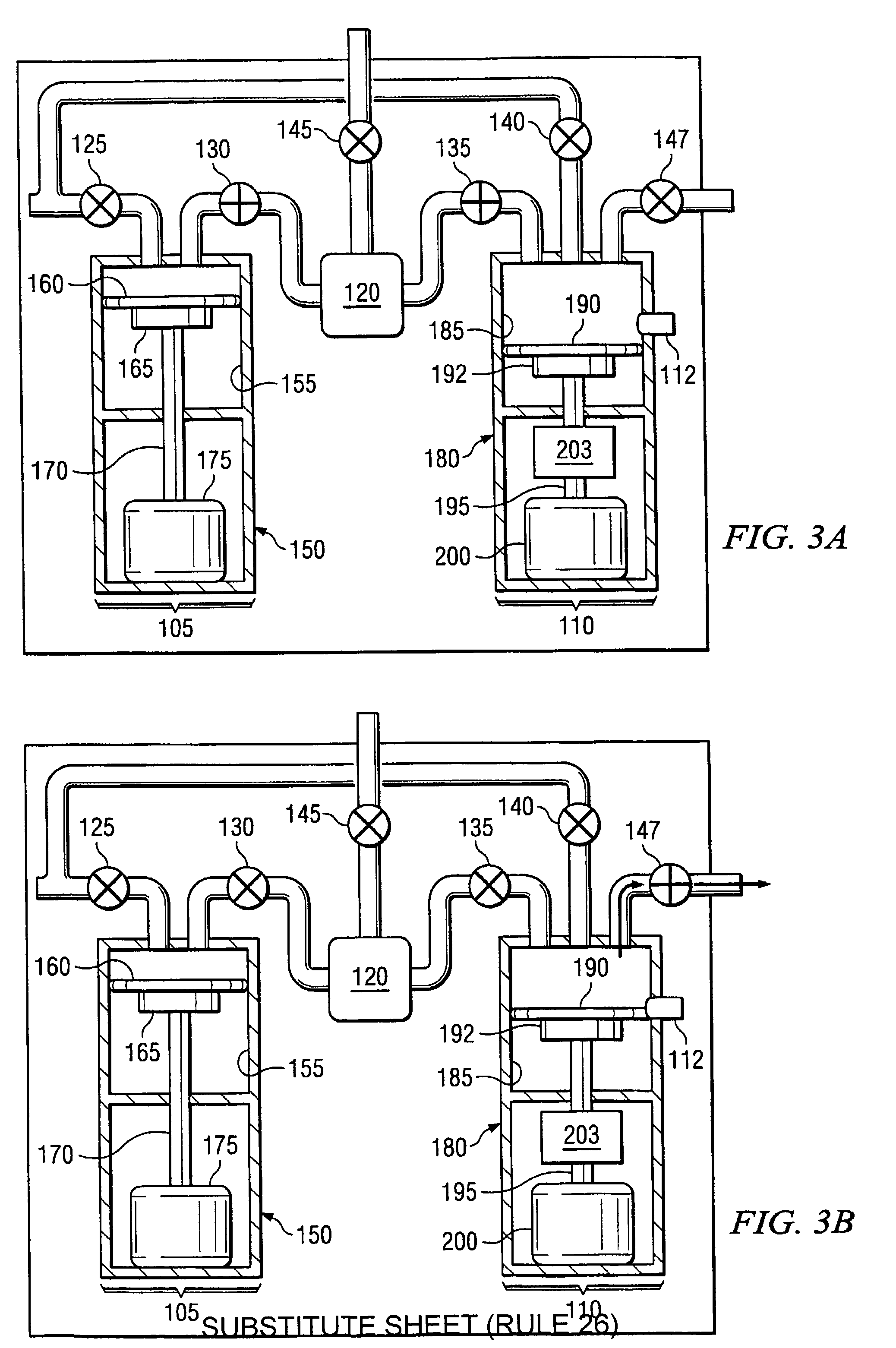
[0026]Preferred embodiments of the invention are illustrated in the FIGURES, like numerals being used to refer to like and corresponding parts of the various drawings.

[0027]Embodiments of the present invention provide a system and method for reducing the hold-up volume of a pump. More particularly, embodiments of the present invention provide a system and method for determining a home position to reduce hold-up volume at a dispense pump and / or a feed pump. The home position for the diaphragm can be selected such that the volume of the chamber at the dispense pump and / or feed pump contains sufficient fluid to perform the various steps of a dispense cycle while minimizing the hold-up volume. Additionally, the home position of the diaphragm can be selected to optimize the effective range of positive displacement.

[0028]FIG. 1 is a diagrammatic representation of a pumping system 10. The pumping system 10 can include a fluid source 15, a pump controller 20 and a multiple stage (“multi-sta...


PUM


Abstract

Embodiments of the present, invention provide a system and method for reducing the hold-up volume of a pump. More particularly, embodiments of the present invention provide a system and method for determining a home position to reduce hold-up volume at a dispense pump and / or a feed pump. The home position for the diaphragm can be selected such that the volume of the chamber at the dispense pump and / or feed pump contains sufficient fluid to perform the various steps of a dispense cycle while minimizing the hold-up volume. Additionally, the home position of the diaphragm can be selected to optimize the effective range of positive displacement.

Description

RELATED APPLICATIONS[0001]The present application claims under 35 U.S.C. § 119(e) the benefit of and priority to U.S. Provisional Patent Application 60 / 630,384, entitled “System and Method for a Variable Home Position Dispense System” by Laverdiere et al., filed Nov. 23, 2004, which is hereby fully incorporated by reference herein.TECHNICAL FIELD[0002]Embodiments of the present invention generally relate to pumping systems and more particularly to dispense pumps. Even more particularly, embodiments of the present invention provide systems and method for reducing the hold-up volume for a dispense pump.BACKGROUND[0003]Dispense systems for semiconductor manufacturing applications are designed to dispense a precise amount of fluid on a wafer. In one-phase systems, fluid is dispensed to a wafer from a dispense pump through a filter. In two-phase systems, fluid is filtered in a filtering phase before entering a dispense pump. The fluid is then dispensed directly to the wafer in a dispense...

Claims


Application Information

Patent Timeline
IPC IPC(8): G05D7/00G01F11/00B67D7/30
CPCF04B13/00F04B49/065F04B43/02F04B2205/09F04B2201/0201H01L21/00H01L21/02
Inventor LAVERDIERE, MARCCEDRONE, JAMESGONNELLA, GEORGEGASHGAEE, IRAJMAGOON, PAULKING, TIMOTHY J.
Owner ENTEGRIS INC
Learn More