System and method for at-nozzle injection of agrochemicals

a technology of at-nozzle injection and agrochemicals, which is applied in the direction of electrochemical generators, transportation and packaging, liquid transfer devices, etc., can solve the problems of poor crop yield, adverse environmental injuries, and ineffective application, and achieve the effect of increasing costs, improving the yield of crops, and improving the effect of application

Active Publication Date: 2009-05-28
RGT UNIV OF CALIFORNIA
View PDF9 Cites 65 Cited by
  • Summary
  • Abstract
  • Description
  • Claims
  • Application Information

AI Technical Summary

Benefits of technology

[0020]The present invention provides a system and method for metering and injecting an additive, such as a stream of liquid, into a carrier fluid as the carrier fluid is supplied to a spray nozzle or dispensing device. The system and method use a nozzle with at least one embedded Venturi as a foundation for at-nozzle injection, which offers control over injection amount and mixing prior to discharge. The system can, but not necessarily exclusively, use “air induction” nozzles as the injection device. The system can provide a simplicity and robustness not found in existing and previous spray liquid injection systems.
[0024]According to the present invention, nozzles containing a Venturi are used to combine controlled amounts of an additive, such as an agrochemical, with a carrier fluid prior to discharge. The present inventor discovered that the nozzles can be used as simple robust injection components, with the pumping and metering functions achieved by the Venturi passages. In such a use, injection can be achieved at each nozzle simultaneously and through the use of low pressure, inherently safe liquid supply plumbing.
[0025]It was further discovered that the Venturi-based, air induction nozzles can provide a self regulating system where the concentration of injected fluid in the spray stream emitted from the nozzle can be maintained at a constant level even as the carrier fluid flow rate varied.
[0028]In another embodiment, a metering orifice is introduced between the fluid connection into the spray nozzle Venturi inlet and the injected fluid supply reservoir. The metering orifice determines the relative flow rate between the carrier fluid and the injected fluid and thereby controls the concentration of injected fluid in the dispensed spray liquid from the nozzle.
[0029]In another embodiment, an electronic throttling valve is used to alter the effective metering orifice between the nozzle Venturi inlet and the injected fluid reservoir. In this manner, the ratio of flow rate of carrier fluid through the nozzles and flow rate of injected fluid into the nozzle is controlled, thereby controlling the concentration of the injected fluid in the spray fluid dispensed from the spray nozzle.
[0036]In still another embodiment of the present invention, each dispensing nozzle can include a plurality of Venturis, where each Venturi is used to inject a separate additive into the carrier fluid. For example, two to five Venturis may be placed in series in order to inject two to five additives into the carrier fluid without any premixing of the additives. This enables easy changes of the relative proportions of the different additives as spraying is performed.

Problems solved by technology

Poor spray distribution can limit the efficacy of an application and may lead to adverse environmental injuries, poor crop yields and increased costs.
Once mixed in a central reservoir, the concentration and relative ratios of the individual components in the carrier liquid cannot be altered and the mix may have a limited tank life.
Additionally, some constituents, either active ingredients, inert materials in the pesticide formulations or adjuvants selected by the applicator, may be chemically or physically incompatible and not mix properly.
Additionally, it is sometimes desirable to apply some of the spray liquid components only to certain portions of a crop field to be treated.
In those situations, the entire mix of spray liquid components is not prepared prior to initiating the spray application job.
One disadvantage of some direct injection systems is that the lag time from initiation of an injection chemical rate change to the time when the new rate of chemical actually leaves the nozzles can lead to chemical application rate errors during transient response times.
The fundamental limitation with many commercial injection systems, however, can be due to the basic configuration where the central injection point is located immediately upstream or downstream from the carrier liquid pump.
This results in lengthy hose and pipe distances from the injection point to the nozzles.
The consequence of this configuration is that the time delays between changes in injection rate and the arrival of the altered rate at the nozzles are lengthy and vary from nozzle to nozzle.
Therefore, application rates of the injected materials are non-uniform across the boom and temporally and spatially variable in an unintended and undesirable manner.
However, this configuration is not without considerable challenges; pumping and metering of the injected fluid must be distributed along the spray booms and adequate mixing must occur within the nozzle during a brief time period.
The system provided rapid response for triggered spraying; however, the components were expensive, complex and required a pressurized source of injection liquid near the spray nozzle.
Pressurized lines of highly concentrated pesticide are often considered a potential hazard.
Ambient wind, coupled with small sized droplets, is the prime cause of spray drift.
However, sprayer systems using air induction nozzles have the same problems described heretofore as systems using other types of nozzles.

Method used


Image

  • System and method for at-nozzle injection of agrochemicals
  • System and method for at-nozzle injection of agrochemicals
  • System and method for at-nozzle injection of agrochemicals

Examples


example 1

[0088]The nozzle used in this example was a 110 degree fan angle, Venturi flat fan nozzle (AI 11004, TeeJet, Spraying Systems, Inc.). Inserted into the two air inlet ports of the integrated Venturi were barbed connectors leading to 50 cm of plastic tubing (1.6 mm i.d.). The plastic tubing terminated into a standard threaded nozzle body assembly (CP1322 ¼TT, TeeJet, Spraying Systems, Inc.) into which a range of orifice metering plates were installed. The metering plates were standard commercial components (CP 4916 Series, TeeJet, Spraying Systems, Inc.) with orifice diameters of 0.20, 0.38, 0.76, 1.54 and 3.05 mm (Plate Nos. 8, 15, 30, 61 and 120, respectively, Spraying Systems, Inc.). The carrier liquid, supplied to the liquid inlet of the nozzle, for all experiments was de-ionized water and the injected liquids, supplied to the air induction ports, were de-ionized water, a 0.25% v / v surfactant solution (Triton X-100, Fisher Scientific) in de-ionized water and a 0.25% v / v polymer so...

example 2

[0100]In this example an array of 6 nozzles was fabricated in a linear spray boom with 20 inches between each nozzle. A system of spray collectors was devised to capture the emitted spray on a plane 20 inches below the exit tips of the spray nozzles. The spray discharge was collected in 1.5 inch increments along the plane. This provided a measure of the uniformity of the spray mix along the entire 120 inch spray pattern created by the 6-nozzle spray boom. Salt tracer was added to the injected fluid as discussed in Example 1. The measurement techniques used in Example 1 were also used for this example.

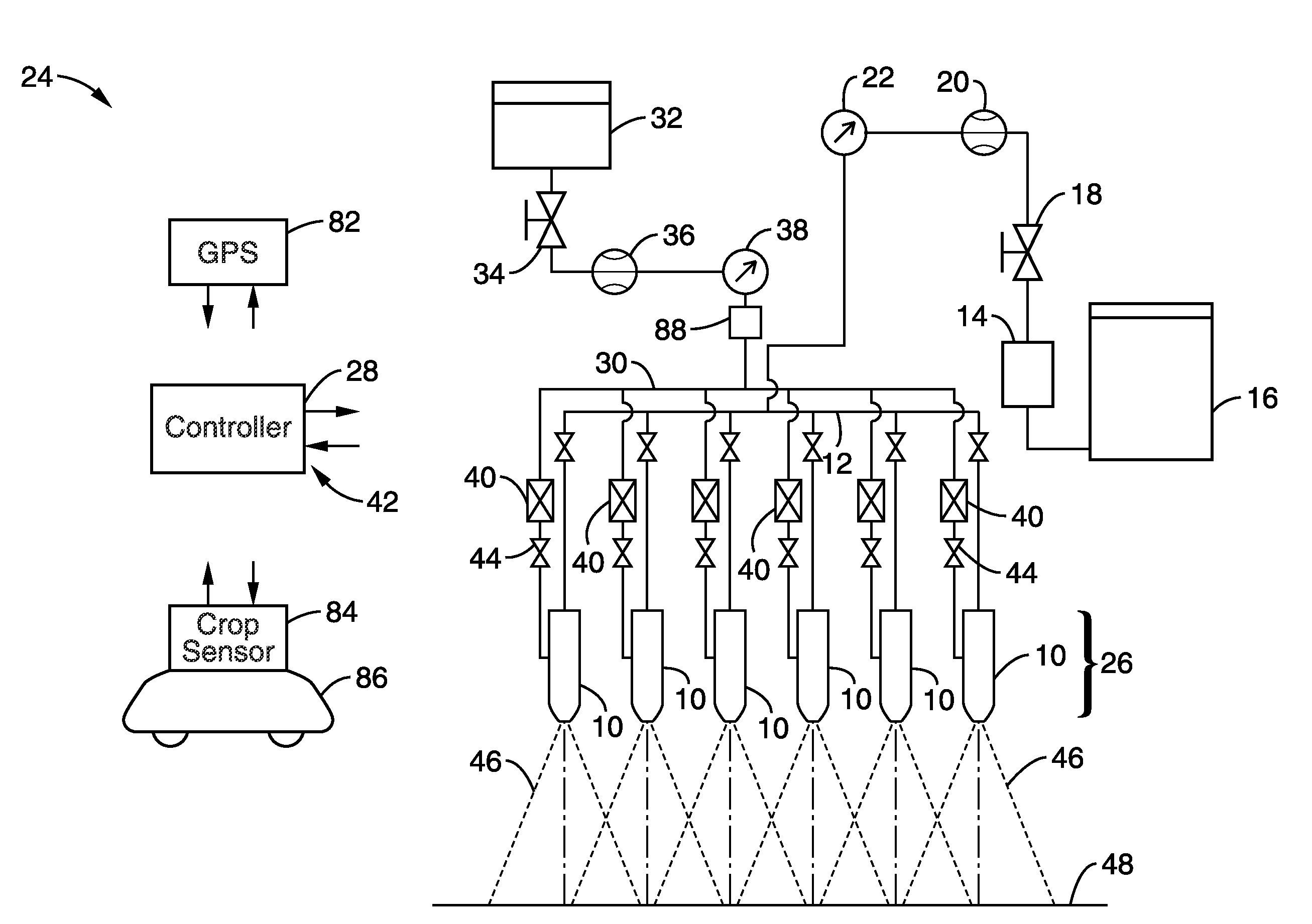
[0101]The system was fabricated as illustrated in FIG. 1. The nozzles were AI 11008 nozzles (Spraying Systems, Inc.) and operated at a carrier liquid pressure of 2 bar. In the first set of tests, the nozzles were configured similarly as shown in FIG. 2 with an injection line directed to each side of the Venturi inlet. The test orifices were Nos. 10, 20 and 41 as described in Example 1.

[...

example 3

[0105]It is desirable to have an active control over the flow rate of the injected liquid into the Venturi passage in the nozzle. This would provide a means for adjusting the application rate of active ingredient contained in the injected liquid. In this example, the system shown in FIG. 1 was tested. A controllable needle metering valve was used to alter the injection rate of liquid into the nozzles. A No. 41 metering orifice plate was installed as orifice plate assembly.

[0106]In the first test, 6 AI 11008 nozzles were operated as described in Example 2. Spray tracer fluid was used as in Example 2. However, rather than manually changing the orifice plates to adjust injection flow rate, the needle valve was manually closed until the flow rate on flowmeter was observed to match that obtained then orifice plates 10 and 20 were installed at location.

[0107]The results are shown in FIG. 15. Injection rates and resulting spray concentrations equivalent to those achieved by replacing the m...


PUM


Abstract

A system and method for combining an additive with a carrier fluid in a spray nozzle. The carrier fluid is fed to one or more nozzles that include an embedded Venturi. The Venturi includes an induction port connected to an additive supply. As the carrier fluid flows through the nozzle, the flow creates a vacuum or suction force that draws in the additive. Of particular advantage, the concentration of the additive combined with the carrier fluid can be maintained constant even if the flow rate of the carrier fluid varies. The system and process are particularly well suited for spraying fields, such as crop fields or orchards, with an agrochemical.

Description

CROSS-REFERENCE TO RELATED APPLICATIONS[0001]This application is based on and claims priority from U.S. provisional application Ser. No. 60 / 989,944 filed on Nov. 25, 2007, incorporated herein by reference in its entirety.STATEMENT REGARDING FEDERALLY SPONSORED RESEARCH OR DEVELOPMENT[0002]Not ApplicableINCORPORATION-BY-REFERENCE OF MATERIAL SUBMITTED ON A COMPACT DISC[0003]Not ApplicableBACKGROUND OF THE INVENTION[0004]1. Field of the Invention[0005]This invention pertains generally to liquid sprayer systems and more particularly to the on-demand metering, mixing, atomization and dispersal of a number of liquid components in a single spray liquid mixture.[0006]2. Description of Related Art[0007]Modern agriculture is becoming increasingly dependent on the efficient and accurate application of liquid fertilizers and crop protection agents in order to be profitable and environmentally responsible. Agricultural chemicals may be applied as sprays of liquid solutions, emulsions or suspens...

Claims


Application Information

Patent Timeline
Patent Type & Authority Applications(United States)
IPC IPC(8): B05B7/30B67D7/08
CPCA01M7/006A01M7/0092B01F5/0413B01F5/0418B05B7/0433B01F5/0428B05B7/0408B05B7/0425B01F5/0423B01F25/3123B01F25/31233B01F25/31242B01F25/312
Inventor GILES, DURHAM K.
Owner RGT UNIV OF CALIFORNIA
Why Eureka
Try Eureka