

Flameless thermal oxidation method
a thermal oxidation and flameless technology, applied in the field of flameless thermal oxidation, can solve the problems of reducing the open volume available for the flow of the process stream, nox and co, and nox and co production, and achieves a substantial pressure drop
- Summary
- Abstract
- Description
- Claims
- Application Information
AI Technical Summary
Benefits of technology
Problems solved by technology
Method used
Image

Examples
example 1
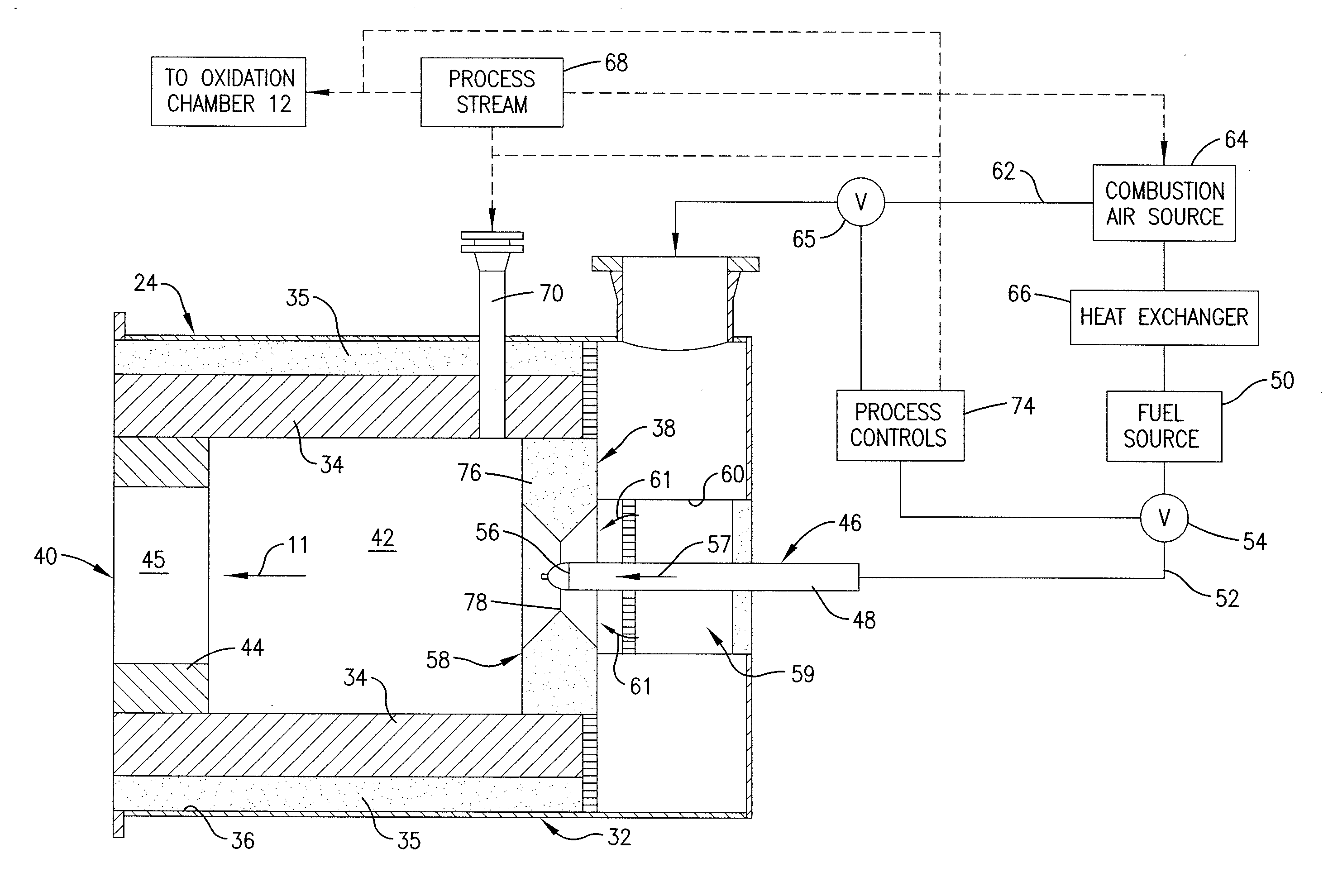
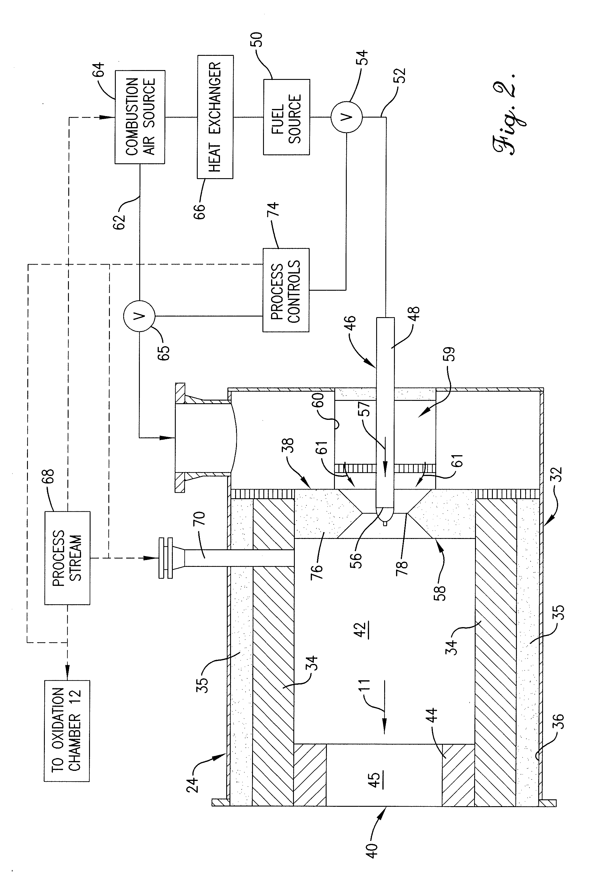
[0037]Combustion air in the form of air at room temperature was delivered into the burner chamber 42 through swirl vanes 60 at a flow rate of 114,000 scf / hr. Fuel in the form of natural gas at room temperature was injected into the burner chamber 42 through the fuel tip 56 at a flow rate of 5,550 scf / hr. The fuel and combustion air mixture was ignited and burned with a visible flame until the oxidation chamber 12 reached a temperature of 1,880 degrees F. Once the oxidation chamber 12 was preheated in this manner, the burner flame was extinguished by pulling the fuel tip 56 back from the centerline of the burner throat 78 approximately 3.5 inches to cause more complete mixing of the fuel and combustion air prior to passage of the mixture through the burner throat 78. The fuel and combustion air flow rates remained unchanged and the premix stream of fuel and combustion air passed into the burner chamber 42 through the burner throat 78 without a visible flame being present and the comb...
example 2
[0038]The test of Example 1 was repeated with the following changes in parameters: (1) the combustion air flow rate was reduced to 100,200 scf / hr., and (2) the fuel flow rate through the burner chamber 42 was reduced by staging the fuel. The total fuel flow was 5,500 scf / hr. and was split with 85.6% of the fuel being premixed with all of the combustion air stream prior to injection into the burner chamber 42 and the remaining 14.4% of the fuel being injected through two fuel gas tips positioned in the oxidation chamber 12 just downstream from the burner 24. The fuel injected through the fuel gas tips into the oxidation chamber 12 was combusted with a visible flame and provided direct heating of the refractory lining 16 to stabilize the flameless oxidation process in the oxidation chamber 12. As a result of this increased heat input, the outlet temperature of the oxidation chamber 12 was 1,990 degrees F. As a result of the combustion of a portion of the fuel with a visible flame, the...
PUM
| Property | Measurement | Unit |
|---|---|---|
| time | aaaaa | aaaaa |
| flow rate | aaaaa | aaaaa |
| flow rate | aaaaa | aaaaa |
Abstract
Description
Claims
Application Information