Guided wave pipeline inspection system and method with enhanced natural focusing techniques

a pipeline and guided wave technology, applied in the field of pipeline inspection, can solve the problems of difficult interpretation, long-range ultrasonic guided wave inspection systems are currently difficult to use, and are a bit time-consuming

Inactive Publication Date: 2009-06-04
FUKUOKA BROADCASTING CORPORATION
View PDF15 Cites 45 Cited by
  • Summary
  • Abstract
  • Description
  • Claims
  • Application Information

AI Technical Summary

Benefits of technology

[0005]It is therefore an objective of an aspect of the invention to provide a reliable method and apparatus for detecting small defects in piping from 0.1 % to 3% CSA.

Problems solved by technology

Quite often, however, it is not possible to use ILI.
These Long Range Ultrasonic Guided Wave Inspection Systems are currently difficult to use and somewhat time consuming as well.
If this does not occur, the mode will either not be excited at all of the excitation frequencies, or the velocity will change with frequency, and make interpretation difficult.
The wave mode conversions at elbow regions may cause false alarms and decrease inspection energy.
If this is untrue, the mode will either not be excited, or the velocity will change with frequency, and make interpretation difficult.

Method used


Image

  • Guided wave pipeline inspection system  and method with enhanced natural focusing techniques
  • Guided wave pipeline inspection system  and method with enhanced natural focusing techniques
  • Guided wave pipeline inspection system  and method with enhanced natural focusing techniques

Examples


Embodiment Construction

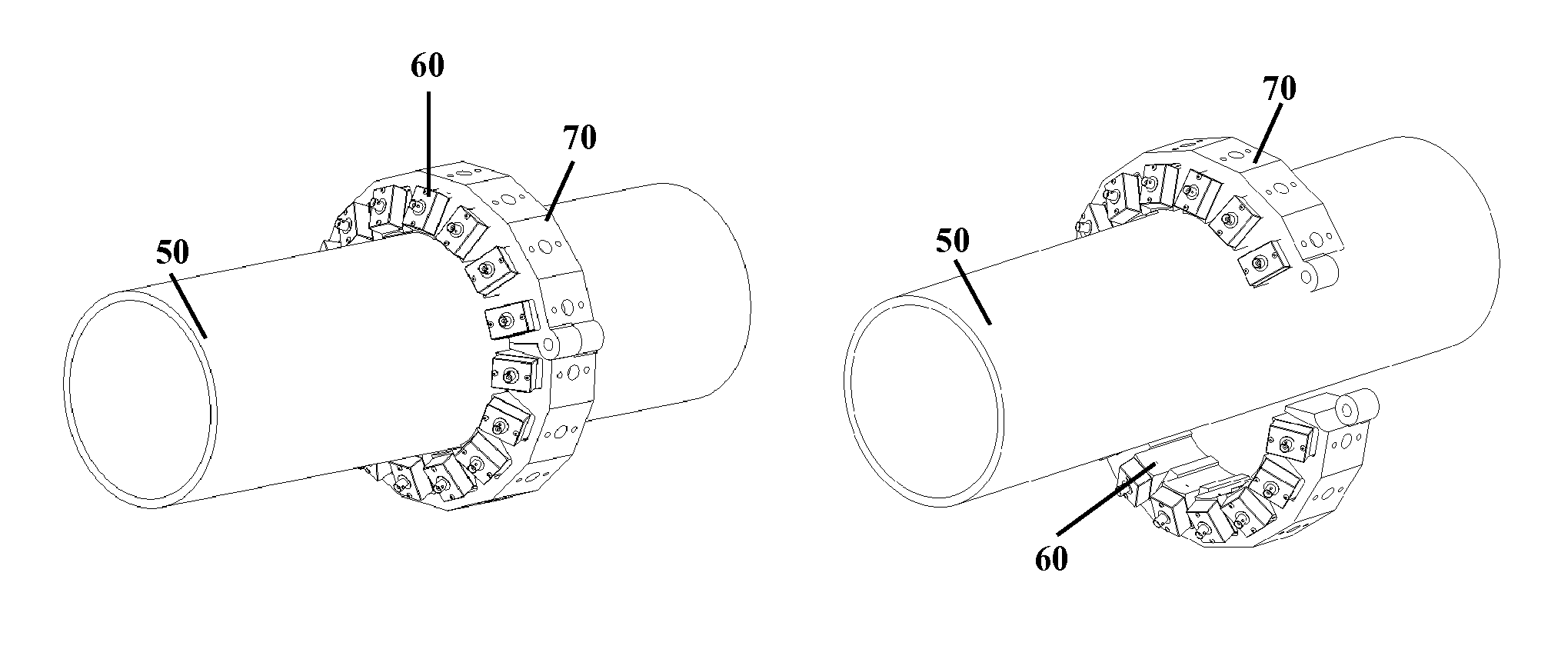
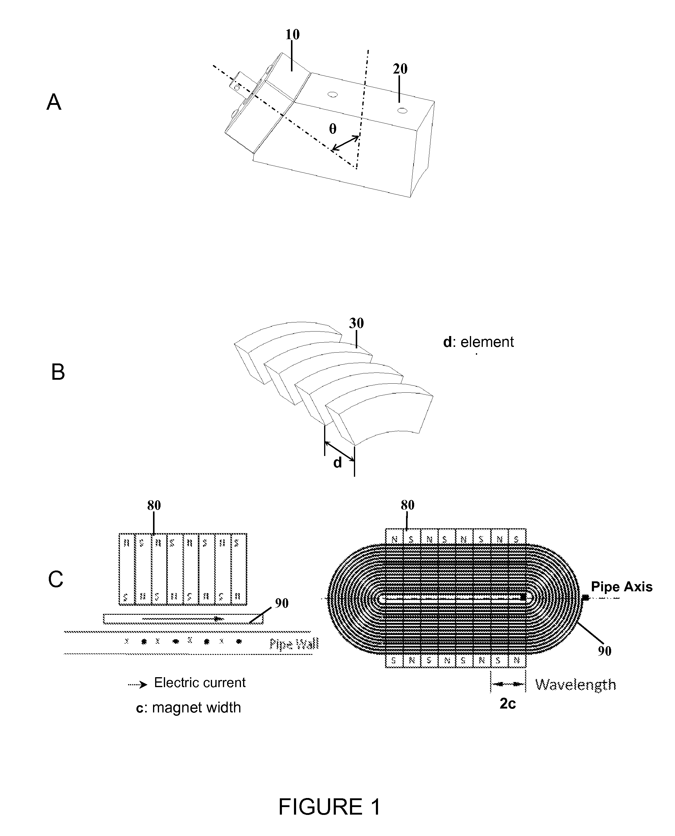
[0059]Referring to FIGS. 1A, 1B, and 1C, in an example embodiment of the invention, three different types of transducers that include angle beam transducers, comb transducers, and electromagnetic acoustic transducers (EMATs), can be used to generate selected guided wave modes in a structure, in this example, a pipe. An ultrasonic longitudinal transducer 10 mounted on an angle beam wedge 20 is called an angle beam transducer, which excites guided waves with a constant phase velocity with a particular incident angle. Individual elements 30 may be placed along an element spacing d along the axis of pipe 90 to be investigated.

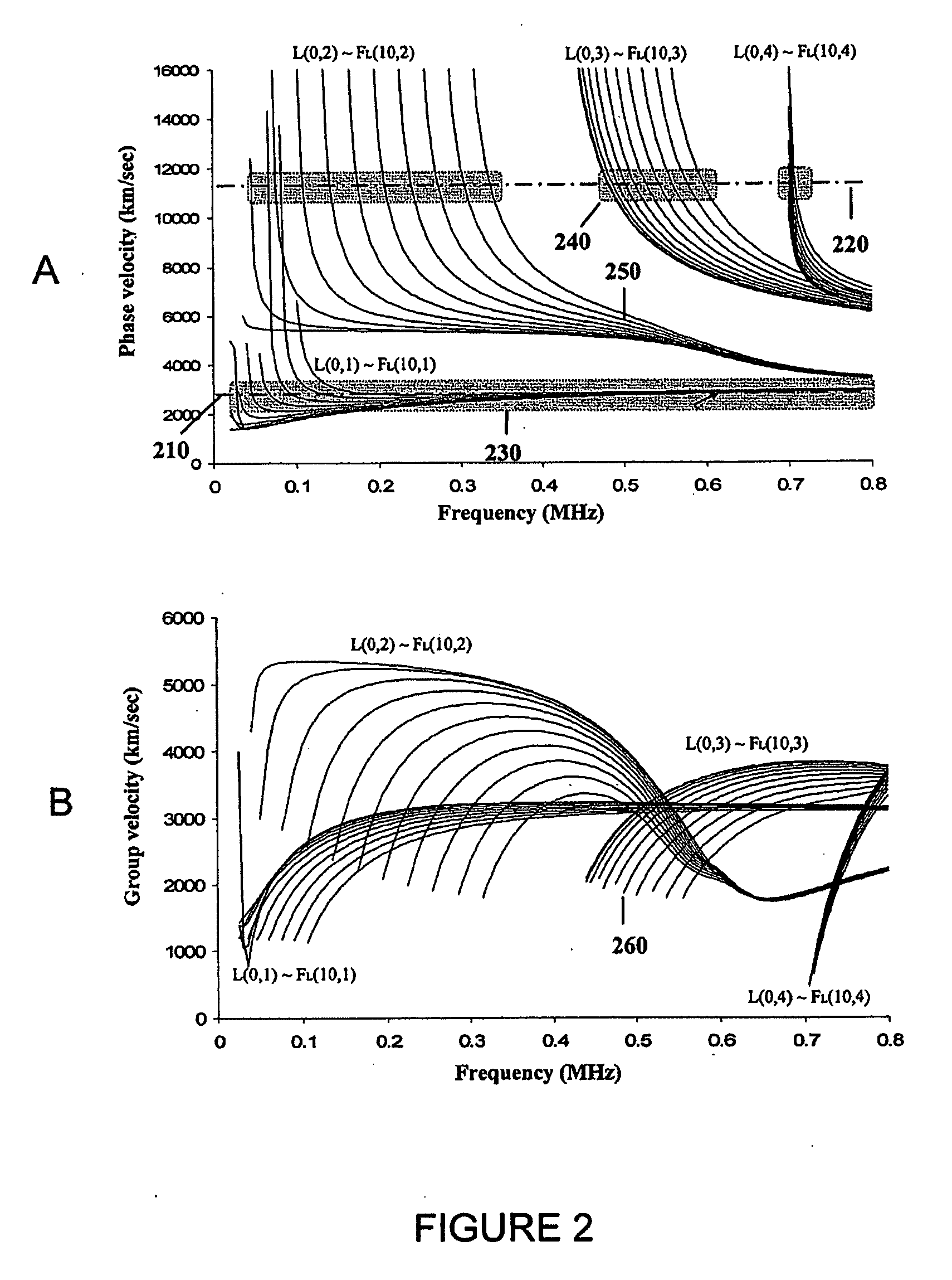
[0060]Referring to FIG. 2A, excitation lines 210, 220 of two angle beam transducers placed on a pipe with different incident angles excite the longitudinal axisymmetric and flexural modes within the excitation zones 230, 240. Excitation zones exist at the cross of the excitation lines and phase velocity dispersion curves 250. If being excited simultaneously, a long...


PUM

PropertyMeasurementUnit
frequencyaaaaaaaaaa
frequenciesaaaaaaaaaa
frequencyaaaaaaaaaa

Abstract

A method for the nondestructive inspecting of coated or uncoated pipeline, using ultrasonic guided waves excited on the outer or inner pipe surface, wherein at least one or more transducers are individually or simultaneously excited to generate ultrasound, wherein multiple received signals with different focal spot positions are processed and combined to produce a reduced number of final waveforms that show defect axial positions in the pipe, wherein a data calibration scheme is utilized to adjust velocity variability for all the guided wave modes at different frequencies, and wherein the hardware arrangement has at least one pulser channel and one receiver channel for the collection and storage of signals.

Description

CROSS REFERENCE TO RELATED APPLICATIONS[0001]The present application claims priority under 35 U.S.C. 119(e) to U.S. Provisional Patent Application 60 / 991,947 filed on Dec. 3, 2007, the entirety of which is incorporated by reference herein.FIELD OF THE INVENTION[0002]Aspects of the invention relate to pipeline inspection. More specifically, aspects of the invention relate to providing a quick, easy-to-use, guided wave pipeline inspection system and method to detect small defects, with varying frequencies, for example from 150 kHz to 800 kHz. The system utilizes enhanced frequency tuning, natural focusing techniques, and multi-mode detection capabilities.BACKGROUND INFORMATION[0003]Corrosion is one of the primary preventable causes of failure in refinery, petrochemical, and other pipelines. Cracking is also possible. Defects in pipelines have various shapes and locations. The defects, therefore, may be detectable for some guided waves at particular frequencies but non-detectable for o...

Claims


Application Information

Patent Timeline
Patent Type & Authority Applications(United States)
IPC IPC(8): G01N29/04
CPCG01N29/2412G01N29/30G01N2291/2636G01N2291/0425G01N2291/2634G01N29/50
Inventor OWENS, STEVEN E.ZHANG, LIROSE, JOSEPH L.
Owner FUKUOKA BROADCASTING CORPORATION
Why Eureka
Try Eureka