Method and circuit arrangement of the supply of pressue medium to at least two hydraulic consumers

a technology of pressure medium and hydraulic consumer, which is applied in the direction of fluid coupling, servomotor, coupling, etc., can solve the problems of reducing the efficiency of the system, so as to achieve optimal compromise between energy efficiency and dynamics, and minimize the effect of mutual influence of various simultaneously operated consumers

Inactive Publication Date: 2009-06-11
SAUER DANFOSS NORDBERG
View PDF6 Cites 19 Cited by
  • Summary
  • Abstract
  • Description
  • Claims
  • Application Information

AI Technical Summary

Benefits of technology

[0010]e) superposition of the control of the directional valve of the consumer having the highest load by at least one dynamic subcontroller which smoothes out pressure fluctuations via the residual opening of the directional valve remaining between the valve-spool positions y1 and y1,max.
[0011]It is therefore proposed, in the system described in the introduction, to depart somewhat from the aim of maximum energy saving and not to open completely the valve belonging to the consumer having the highest load, but, instead, to open it only to a large extent. Fixing the operating point of the valve in this way below its full opening creates an, albeit minor, inflow pressure difference. The directional valve with its good dynamics is then available as an actuator and can compensate disturbances using the remaining residual opening. Setpoint changes, must, of course, continue to be compensated by the displacement control of the pump which also ensures the stationary accuracy of the volume flow.
[0012]It is advantageous if, in addition, maximum-pressure control is provided, which, when a preset pressure is reached, overrides the displacement control of the pump. The displacement is thereby set such that the maximum pressure is held, but is not overshot.
[0013]Preferably, a dynamic subcontroller is assigned to the consumer valve on the load side. At increasing pressure in the load line, its output is superposed additively to the valve signal in a way, that the spool position is increasing. Thus, sudden load changes will be compensated directly at the valve. If another dynamic subcontroller is added to the valve on the pump side, also pressure disturbances will be compensated which are caused by load changes at one of the other consumers. The output of this second subcontroller is superposed subtractively to the valve signal, so that the valve opening is decreasing when the pump pressure is rising. Thus the mutual influencing of various simultaneously operated consumers can be minimized. These dynamic subcontrollers preferably react to the rate of pressure change. If the pressure does not change or changes only slowly, the output signal from the subcontrollers is zero. Pressure peaks occurring generate an output signal which is superposed on that of the stationary-value control element of the valve control and which therefore smoothes out the pressure peaks directly at the directional valve. The dynamic subcontrollers are parameterizable and consequently adaptable to the individual time constants of different consumers.

Problems solved by technology

In electronically implemented load-sensing (LS) systems for the supply of a plurality of hydraulic consumers, the energy efficiency can not only be improved by lowering the LS pressure difference.
In the known systems, although it is possible to minimize energy losses, there is also nevertheless the disadvantage that the highest loaded consumer is controlled by the displacement of the variable-displacement pump.
However, in comparison with valve controls, pump displacement controls have, relatively low dynamics, resulting in undesirable consequences.
Thus, sudden fluctuations in the load pressure of the consumer subjected to the highest load can be smoothed out only inadequately.
Moreover, load-pressure fluctuations of consumers subjected to lower load may penetrate to the pump side in spite of high-speed individual pressure balances.
If these consumers have very low time constants, as is the case, for example, in motors with low mass inertia and short hydraulic lines, an influencing of the pump pressure then cannot be avoided entirely.
In this case, too, the disturbance at the consumer subjected to the highest load can then be smoothed out only inadequately slowly by means of sluggish pump adjustment.

Method used


Image

  • Method and circuit arrangement of the supply of pressue medium to at least two hydraulic consumers
  • Method and circuit arrangement of the supply of pressue medium to at least two hydraulic consumers
  • Method and circuit arrangement of the supply of pressue medium to at least two hydraulic consumers

Examples


Embodiment Construction

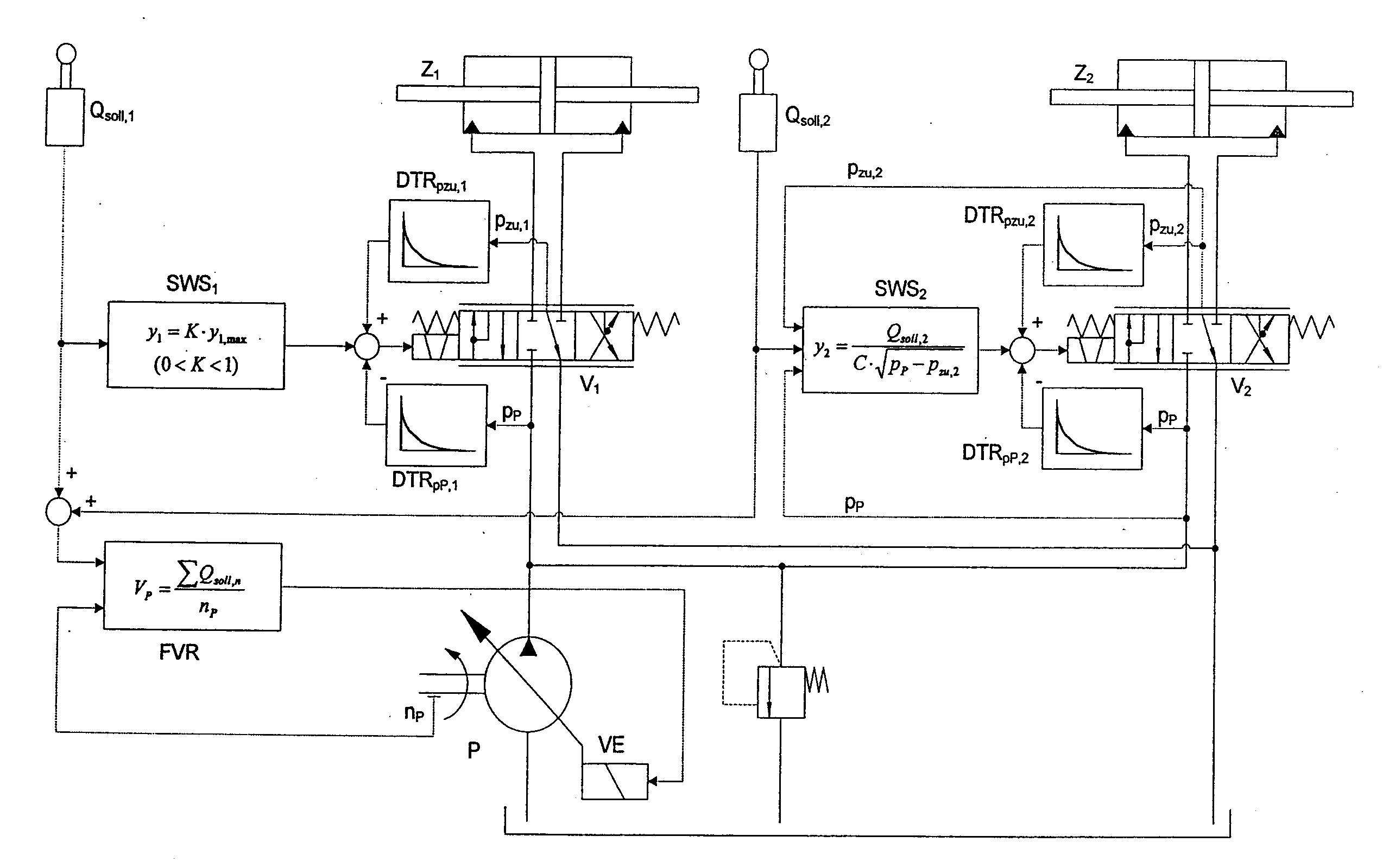
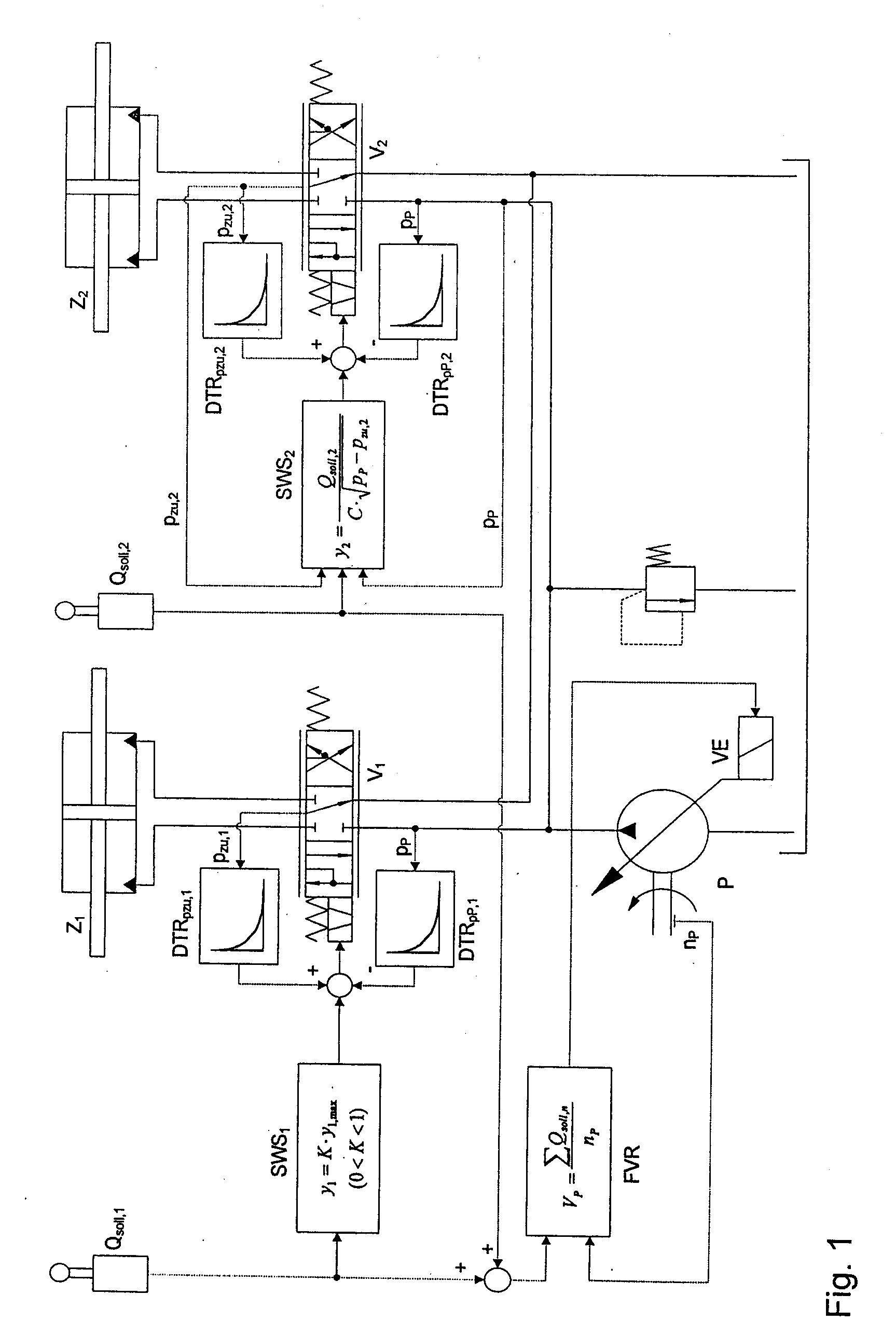
[0018]FIG. 1 shows an exemplary embodiment of the invention. The essential elements of the hydraulic circuit and of the electronic signal flow are in this case illustrated jointly, specifically by the example of two consumers, of which the first consumer Z1 stands for that with the highest load pressure and the second consumer Z2 represents, where appropriate, a plurality of consumers having a lower load pressure.

[0019]A pump P, driven for example by a diesel engine, not illustrated, rotates at the rotational speed nP. The pivot angle (and thus the displacement volume) of the pump P can be controlled via an electrically actuatable adjustment device VE. This regulation takes place by means of the displacement controller FVR according to the sum of the required flows QS011,1, and QS011,2 the displacement volume of the pump VP being regulated, taking into account the rotational speed of the pump nP, to

VP=∑Qsoll,nnP

[0020]This setup allows to adjust flow and pressure in quasi-stationary ...


PUM


Abstract

The invention relates to a method and a circuit arrangement for controlling and regulating the supply of pressure medium to at least two hydraulic consumers, which are assigned in each case a directional valve for setting the flow and a setpoint signal source, by means of a pump with a variable displacement, which can be regulated by means of a displacement controller. The pump displacement is regulated according to the flow required by the setpoint signals. The individual load pressure of the consumers and of the consumer having the highest load pressure are determined. The directional valve of the highest loaded consumer is controlled to a valve-spool position y1, with y1=K·y1,max=const., which lies by a factor K, with 0<K<1, below the valve-spool position y1,max representing the maximum opening of the directional valve. This control of the directional valve of the highest loaded consumer has superposed on it at least one dynamic subcontroller which smoothes out pressure fluctuations via the residual opening of the directional valve remaining between the valve-spool positions y1 and y1,max.

Description

BACKGROUND OF THE INVENTION[0001]The invention relates to a method for the supply of pressure medium to at least two hydraulic consumers according to Claim 1 and to a circuit arrangement according to Claim 15.[0002]In electronically implemented load-sensing (LS) systems for the supply of a plurality of hydraulic consumers, the energy efficiency can not only be improved by lowering the LS pressure difference. The control strategy can, furthermore, be modified such that the valve assigned to the currently highest loaded consumer is opened fully and the pump is regulated to a displacement, which, at the current rotational speed, satisfies the volume flow requirement of all the consumers. In the case of the further consumers, for example, an individual pressure balance then ensures that these do not consume more than the volume flow pertaining to them. Systems of this type are known from DE 103 40 993 A1 or EP 1 664 551 A1.[0003]In the known systems, although it is possible to minimize ...

Claims


Application Information

Patent Timeline
Patent Type & Authority Applications(United States)
IPC IPC(8): F15B13/06
CPCF15B11/161F15B2211/78F15B2211/20546F15B2211/255F15B2211/30525F15B2211/3144F15B2211/327F15B2211/6309F15B2211/6313F15B2211/633F15B2211/6346F15B2211/6652F15B2211/6654F15B2211/71F15B2211/75F15B21/087
Inventor ESDERS, HANSKAISER, STEPHAN
Owner SAUER DANFOSS NORDBERG
Why Eureka
Try Eureka