Apparatus for controlling variable valve device

a variable valve and actuator technology, applied in the direction of valve drives, electrical control, non-mechanical valves, etc., can solve the problems of excessive correction of control signals, insufficient improvement of vvt response, and excessive overshooting of actual valve timing from the target valve timing, etc., to achieve the effect of improving responses

Inactive Publication Date: 2009-06-11
DENSO CORP
View PDF4 Cites 18 Cited by
  • Summary
  • Abstract
  • Description
  • Claims
  • Application Information

AI Technical Summary

Benefits of technology

[0016]According to the embodiment, it is possible to set a proper amount for the offset component, since the offset component is set in accordance with the hydraulic medium temperature. As a result, it is possible to achieve improved responses in both the high temperature and low temperature of the hydraulic medium.
[0017]In one of preferred embodiments, the offset component setting means may set the offset component in order to shift the operating amount outside a dead band where a changing speed of the variable valve device is relatively slow with respect to the operating amount of the control valve. The offset component setting means may set the offset component smaller as the hydraulic medium temperature increases.

Problems solved by technology

Therefore, an improvement in the response of the VVT may be insufficient.
For example, in case that the oil temperature is higher than expected, the control signal may be excessively corrected, and the actual valve timing may overshoot excessively from the target valve timing.
In case that the oil temperature is lower than expected, the control signal may be less corrected, and a response of the VVT is slow.

Method used


Image

  • Apparatus for controlling variable valve device
  • Apparatus for controlling variable valve device
  • Apparatus for controlling variable valve device

Examples


first embodiment

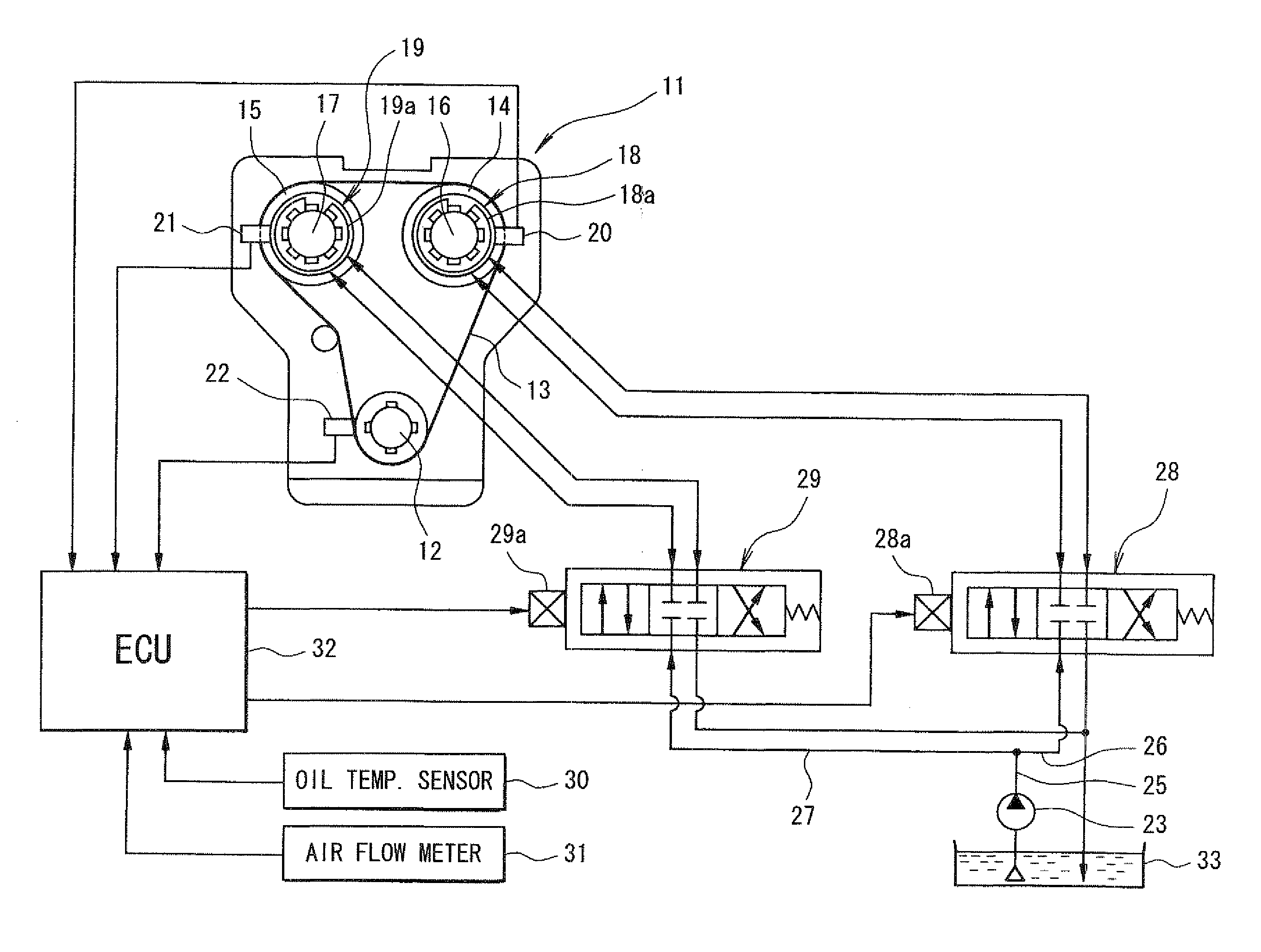
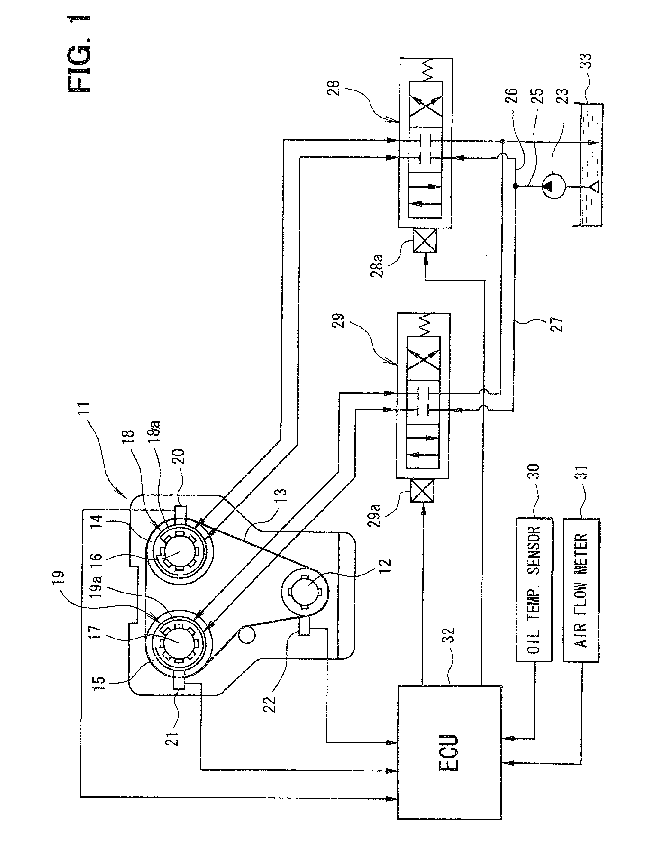
[0037]A first embodiment of the invention is described below with the drawings. The first embodiment is a variable valve timing system. The variable valve timing system is referred to as a VVT system. The VVT system includes a hydraulic system and an electronic control system as a control device. The hydraulic system includes at least one variable valve timing device as a variable valve device, a hydraulic source and control valves. The WT uses a hydraulic pressure to modulate a movement of a valve. The electronic control system for the VVT system includes a plurality of sensors, a control unit and a plurality of actuators. The control valve acts as the actuator.

[0038]Referring to FIG. 1, a configuration of the VVT system is described. FIG. 1 shows a block diagram of the VVT system. The engine 11 is an internal combustion engine having a crankshaft 12. The crankshaft 12 has a crank sprocket engaged with a timing chain 13. The timing chain 13 is also engaged with cam sprockets 14 and...


PUM


Abstract

A variable valve device modulates movement of a valve for internal combustion engine by using a hydraulic pressure. The variable valve device is controlled by a control device via a control valve that modulates hydraulic pressure supply to and discharge from the variable valve device. The control device offsets an operating amount of the control valve by an offset component that shifts the operating amount outside a dead band. The control device sets the offset component smaller as the hydraulic medium temperature increases. The control device sets the offset component smaller when a controlling direction coincides with a biasing direction of a biasing member than that when the controlling direction opposes to the biasing direction. Further, the control device cancels the offset component when the actual valve movement is sufficiently close to the target valve movement.

Description

CROSS REFERENCE TO RELATED APPLICATION[0001]This application is based on Japanese Patent Application No. 2007-316626 filed on Dec. 7, 2007, the contents of which are incorporated herein by reference in its entirety.FIELD OF THE INVENTION[0002]The present invention relates to an apparatus for controlling a variable valve device that varies valve movement by using a hydraulic pressure as a power source.BACKGROUND OF THE INVENTION[0003]Conventionally, number of internal combustion engines equipped with a variable valve device is increasing. Hereinafter, the internal combustion engine is referred to as an engine. The variable valve device is installed in a drive train from a crankshaft to a camshaft that mechanically operates at lest one of an intake valve and an exhaust valve. The variable valve device modulates or varies valve movement, such as a valve opening timing, a valve closing timing, a valve timing, and a valve lift. In one of the variable valve device, the variable valve devi...

Claims


Application Information

Patent Timeline
Patent Type & Authority Applications(United States)
IPC IPC(8): F01L9/02F01L1/34
CPCF01L1/022F01L1/024F01L1/026F01L1/3442F01L2001/0537F02D41/2464F01L2001/3443F01L2001/34483F01L2001/34496F01L2800/00F01L2001/34426
Inventor WADA, MINORUSHIKATA, YASUHIRO
Owner DENSO CORP
Why Eureka
Try Eureka