Eureka AIR delivers breakthrough ideas for toughest innovation challenges, trusted by R&D personnel around the world.

Method for reducing carbon dioxide emissions and water contamination potential while increasing product yields from carbon gasification and energy production processes

a technology of carbon gasification and product yield, which is applied in the direction of combustible gas production, hydrogen sulfide, hydrocarbons, etc., can solve the problems of little driving force to develop the technology to reduce carbon dioxide emissions and little prior art on reducing carbon dioxide at its sour

Inactive Publication Date: 2009-06-11
AHNER PAUL F
View PDF3 Cites 21 Cited by
  • Summary
  • Abstract
  • Description
  • Claims
  • Application Information

AI Technical Summary

Problems solved by technology

As such, there has been little driving force to develop the technology to reduce carbon dioxide emissions.
Little prior art regarding reducing carbon dioxide at its source has been found.
This patent:deals only with a surface industrial coal fired boiler;does not claim a separate carbon dioxide reduction reactor or a separate water-gas shift reactor;does not employ short term carbon dioxide storage or other operational procedures to improve the carbon dioxide reduction potential of the process;does not employ short term gas storage or other operational procedures to improve the water-gas shift performance of the process;does not address the sequestration of the waste carbon dioxide or other substances;does not address the overall flow schemes to maximize the production of synthesis gas while increasing carbon utilization;does not address any aspects of underground carbon gasification;does not address the production of synthesis gas or hydrogen fuel.

Method used


Image

  • Method for reducing carbon dioxide emissions and water contamination potential while increasing product yields from carbon gasification and energy production processes
  • Method for reducing carbon dioxide emissions and water contamination potential while increasing product yields from carbon gasification and energy production processes
  • Method for reducing carbon dioxide emissions and water contamination potential while increasing product yields from carbon gasification and energy production processes

Examples


Embodiment Construction

—FIGS. 1-7

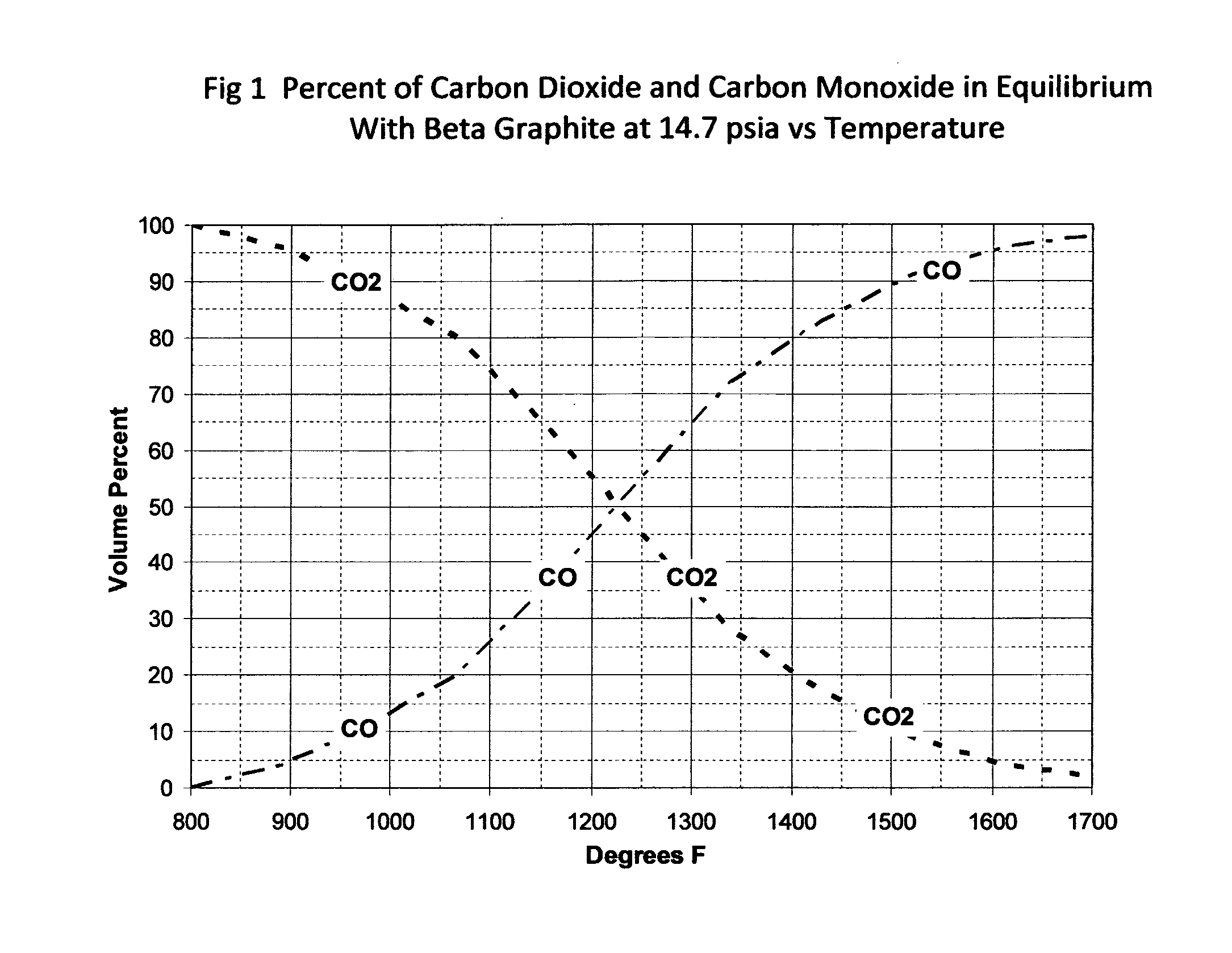
[0078]FIG. 1 is a plot of the equilibrium gas compositions of carbon monoxide and carbon dioxide in the presence of solid phase carbon versus temperature. This figure shows that, the reduction of carbon dioxide to carbon monoxide (Reaction 6) in the presence of elemental carbon is favored at high temperatures.

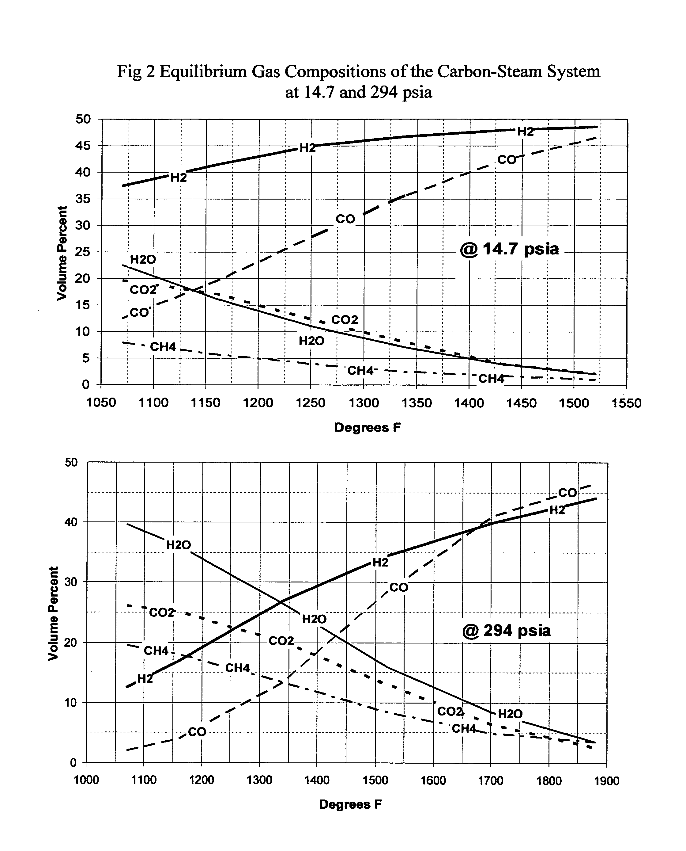
[0079]FIG. 2 is a plot of the equilibrium gas compositions of the carbon / steam system versus temperature at both 0 psig and at 294 psig. This plot reveals that the steam char reaction (Reaction 5) favors the production of carbon monoxide and hydrogen in the same temperature range as the carbon dioxide reduction reaction (Reaction 6). FIG. 2 also reveals that the desired reactions employed in this invention are favored under lower temperature and low pressure conditions. If higher pressures are employed in the process, higher temperatures are required to achieve the same degree of conversion to synthesis gas.

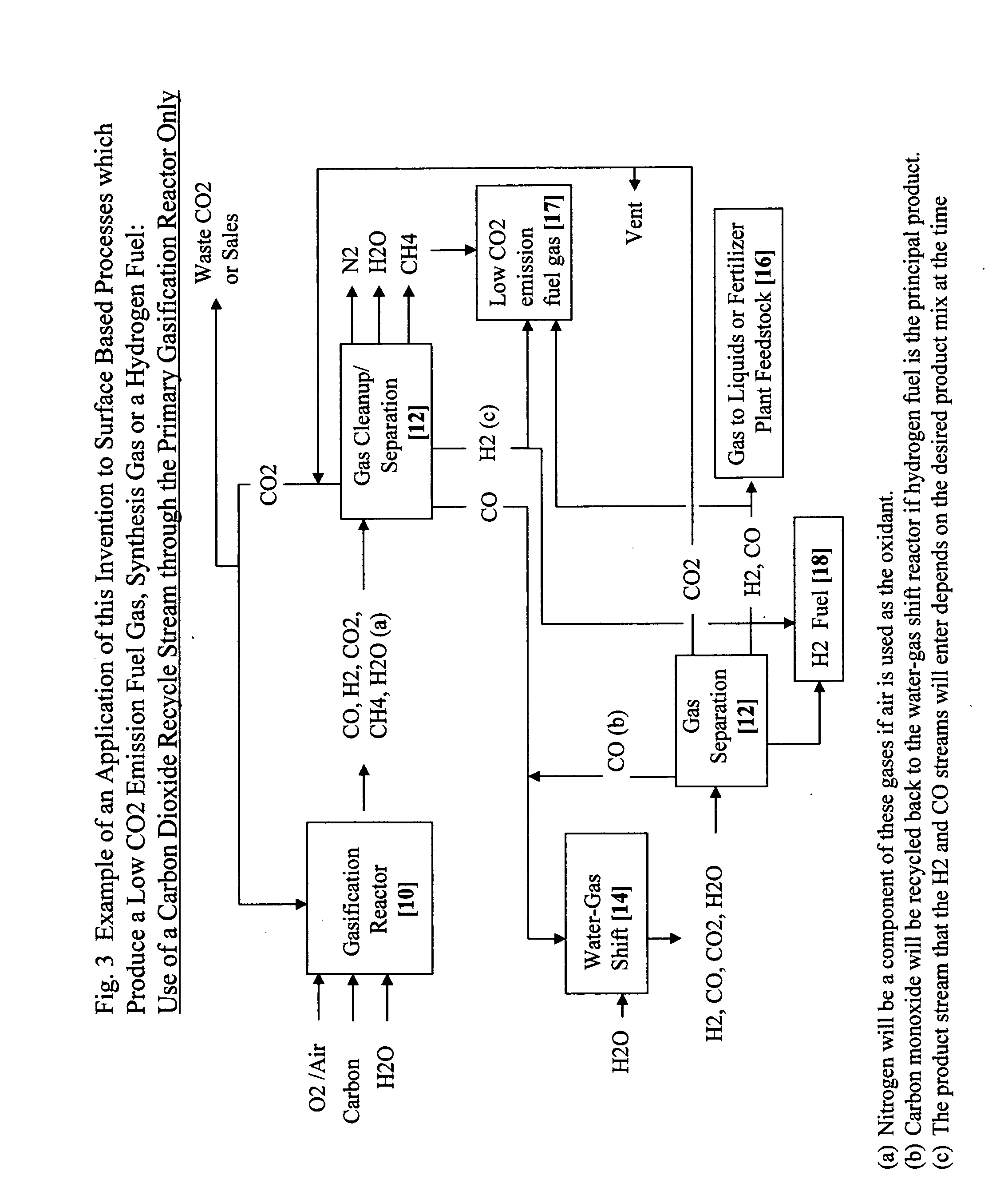
[0080]FIG. 3 illustrates the use of this invention in a surfa...


PUM

PropertyMeasurementUnit
pressureaaaaaaaaaa
pressureaaaaaaaaaa
temperatureaaaaaaaaaa

Abstract

Carbon dioxide from a process which oxidizes a carbon containing feed is separated and reduced to carbon monoxide using a carbon dioxide reduction reactor [22, 26] coupled to a water gas shift reactor [14], to simultaneously reduce carbon dioxide emissions and increase the product yield of clean fuels. In the preferred underground carbon gasification application, these reduction and shift reactions are substantially promoted by utilizing temporary [24] and permanent storage [28] of the carbon dioxide and carbon monoxide coupled with cyclic operational procedures. Additional advantages include carbon dioxide sequestration, removal of contaminants from the groundwater affected by the process and the ability to influence groundwater flow patterns to improve gasification efficiency and reduce potential environmental effects.

Description

[0001]This application claims priority to Provisional Patent No. 61 / 005,634 filed on Dec. 5, 2007BACKGROUND [0002]1. Field of the Invention[0003]This invention describes an improved method for reducing the carbon dioxide emissions and improving product yields from processes which use fossil fuels to generate energy and / or processes which produce low carbon dioxide emission fuel gas, hydrogen fuel, and liquid fuels or fertilizers using synthesis gas as the feedstock. Furthermore, in the underground application of this invention, it will improve process efficiencies, remove certain contaminants from the underground process waters and help control the flow patterns of the groundwater affected by the gasification process. Recent concern in global warming due to greenhouse gas emissions has attracted much attention to reducing the amount of carbon dioxide emitted by man. To date, the principal proposed method of reducing carbon dioxide emissions from a process was to separate it from the...

Claims


Application Information

Patent Timeline
Patent Type & Authority Applications(United States)
IPC IPC(8): B01D53/62C01B3/24C02F1/68C02F3/00
CPCB01D53/62Y02C10/04C01B3/16C01B3/50C01B2203/0283C01B2203/04C01B2203/0465C01B2203/0475C01B2203/048C01B2203/146C01B2203/148C01B2203/86C10J3/00C10J2300/1612C10J2300/1815B01D2257/504Y02P20/151Y02P30/00Y02A50/20Y02C20/40
Inventor AHNER, PAUL F.
Owner AHNER PAUL F
Why Eureka
Eureka Blog
Learn More