Clock, Frequency Reference, and Other Reference Signal Generator with a Controlled Quality Factor

a technology of quality factor and reference signal, applied in oscillator generators, pulse automatic control, angle modulation by variable impedence, etc., can solve the problems of inability to manufacture as part of the same integrated circuit, affecting the quality of additional power dissipation, and comparatively increasing power dissipation, etc., to achieve low phase noise and period jitter, low error, and fast rise and fall time

Active Publication Date: 2009-06-11
INTEGRATED DEVICE TECH INC
View PDF69 Cites 32 Cited by
  • Summary
  • Abstract
  • Description
  • Claims
  • Application Information

AI Technical Summary

Benefits of technology

[0008]Exemplary embodiments of the invention provide a reference signal generator, system and method which provides a superior reference signal, and which is capable of being fully integrated with other electronics. The exemplary reference signal generator and system provides a very accurate reference and / or clock signal, with very low error, very low phase noise and period jitter, and with extremely fast rise and fall times, rendering the exemplary embodiments suitable for highly exacting applications. The exemplary embodiments provide for accurate frequency control over variable parameters such as temperature, fabrication process variation, and IC aging. The exemplary embodiments also provide for a controlled Q factor over a range of tunable or selectable resonant frequencies, such as providing a substantially monotonic and substantially continuous Q factor for adjacent frequency or capacitance states, or providing a substantially constant Q factor for adjacent frequency or capacitance states.

Problems solved by technology

The difficulty with such crystal oscillators is that they cannot be fabricated as part of the same integrated circuit (“IC”) that is to be driven by their clock signal.
For example, because such a processor must be connected through outside circuitry (such as on a printed circuit board (PCB)), power dissipation is comparatively increased.
In applications which rely on a finite power supply, such as battery power in mobile communications, such additional power dissipation is detrimental.
In addition, such non-integrated solutions, by requiring an additional IC, increase space and area requirements, whether on the PCB or within the finished product, which is also detrimental in mobile environments.
Moreover, such additional components increase manufacturing and production costs, as an additional IC must be fabricated and assembled with the primary circuitry (such as a microprocessor).
Other clock generators which have been produced as integrated circuits with other circuits are generally not sufficiently accurate, particularly over fabrication process, voltage, and temperature (“PVT”) variations.
For example, ring, relaxation and phase shift oscillators may provide a clock signal suitable for some low-sensitivity applications, but have been incapable of providing the higher accuracy required in more sophisticated electronics, such as in applications requiring significant processing capability or data communications.
In addition, these clock generators or oscillators often exhibit considerable frequency drift, jitter, have a comparatively low Q-value, and are subject to other distortions from noise and other interference.

Method used


Image

  • Clock, Frequency Reference, and Other Reference Signal Generator with a Controlled Quality Factor
  • Clock, Frequency Reference, and Other Reference Signal Generator with a Controlled Quality Factor
  • Clock, Frequency Reference, and Other Reference Signal Generator with a Controlled Quality Factor

Examples


embodiment 150

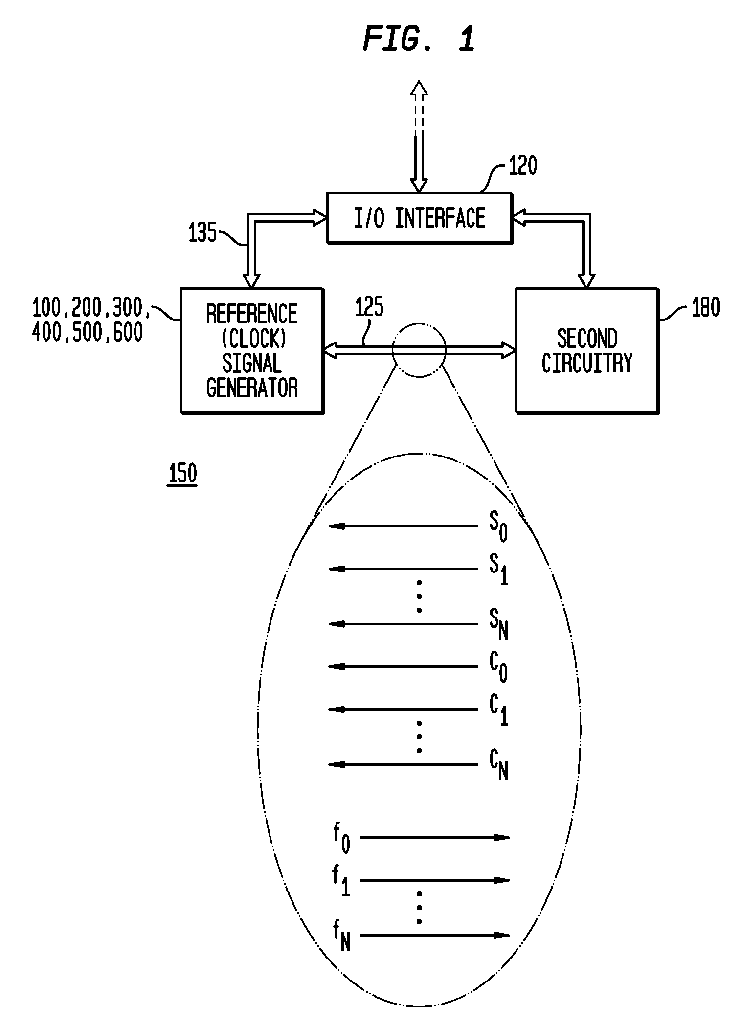
[0065]As indicated above, the various embodiments of the invention provide numerous advantages, including the ability to integrate a highly accurate (over PVT and age), low-jitter, free-running clock generator and / or a timing and frequency reference with other circuitry, such as illustrated in FIG. 1. FIG. 1 is a block diagram illustrating an exemplary first system embodiment 150 in accordance with the teachings of the present invention. The discussion below is also equally applicable to exemplary second and third system embodiments900, 950 is illustrated in FIGS. 32 and 34. As illustrated in FIG. 1, the system 150 is a single integrated circuit, having a reference signal generator 100, 200, 300, 400, 500, 600 (e.g., clock generator and / or timing / frequency reference generator) of the present invention integrated with other, or second, circuitry 180, together with an input / output (I / O) interface 120 or other I / O circuitry. Exemplary reference signal generators 100, 200, 300, 400, 500...

second embodiment

[0149]FIG. 26 is a circuit and block diagram illustrating an exemplary eighth control voltage generator 700 embodiment in accordance with the teachings of the present invention. In this second embodiment, a temperature sensor 705 is utilized, and the first current source (630 or 631) and the second current source (635 or 632) may be either fixed or variable. In a first method of operating the eighth control voltage generator 700, temperature sensor 705 is utilized to determine the actual operating temperature of the reference signal generator 100, 200, 300, 400, 500, 600. Based on the sensed temperature, a memory 710 (as a look up table) is used to select corresponding control coefficients, which then select the amount of resistance of the variable resistance 655, as discussed above. In various embodiments, the sensed temperature may be used to access the memory 710 directly. In other embodiments, the sensed temperature may be converted from an analog to digital value (analog-to-dig...


PUM


Abstract

Exemplary embodiments of the invention provide a reference signal generator having a controlled quality (“Q”) factor. An exemplary apparatus to generate a harmonic reference signal includes a reference resonator, such as an LC-tank, which generates a first reference signal having a resonant frequency, and a plurality of reactance modules couplable to the reference resonator. Each reactance module comprises one or more reactance unit cells, and each reactance unit cell comprises a reactance element coupled in series to a switching element. In exemplary embodiments, the reactance element is a capacitor having a predetermined unit of capacitance, and the switching element is a transistor having a predetermined resistance when in an off state. The ratio of capacitance to resistance is substantially constant for all reactance modules of the plurality of reactance modules.

Description

CROSS-REFERENCE TO A RELATED APPLICATION[0001]This application is a continuation-in-part of and claims priority to U.S. patent application Ser. No. 11 / 950,707, filed Dec. 5, 2007, inventors Scott Michael Pernia et al., entitled “Clock, Frequency Reference, and Other Reference Signal Generator”, which is commonly assigned herewith, the entire contents of which are incorporated herein by reference with the same full force and effect as if set forth in their entirety herein, and with priority claimed for all commonly disclosed subject matter.FIELD OF THE INVENTION[0002]The present invention, in general, relates to reference signal, reference frequency or clocking signal generation, and more particularly, relates to a free-running or self-referenced oscillator or resonator which generates a clock, frequency reference or other reference signal and which has a controlled quality (“Q”) factor over a tunable frequency range.BACKGROUND OF THE INVENTION[0003]Accurate clock generators or timin...

Claims


Application Information

Patent Timeline
Patent Type & Authority Applications(United States)
IPC IPC(8): H03B5/04H03L1/00
CPCH03L1/02H03L5/00H03L7/08H03B5/1228H03B5/1287H03B5/1243H03B5/1265H03B5/1253H03B5/1293H03B5/1215
Inventor O'DAY, JUSTINMCCORQUODALE, MICHAEL SHANNONPERNIA, SCOTT MICHAELNGUYEN, NAM DUCBEAUDOUIN, RALPHKUBBA, SUNDUS
Owner INTEGRATED DEVICE TECH INC
Why Eureka
Try Eureka