Platinum complex compound and organic electroluminescence device using the same

a technology of complex compound and organic electroluminescence device, which is applied in the direction of luminescnet screen of discharge tube, platinum organic compound, organic chemistry, etc., can solve the problem of large chromaticity change of light emission, and achieve the effect of light emission in higher luminance and less chromaticity chang

Inactive Publication Date: 2009-06-18
UDC IRELAND
View PDF3 Cites 48 Cited by
  • Summary
  • Abstract
  • Description
  • Claims
  • Application Information

AI Technical Summary

Benefits of technology

[0007]An object of the invention is to provide an organic electroluminescence device little in chromaticity change due to addition concentration of a phosphorescent material in a light-emitting layer and capable of light emission in higher luminance. Another object is to provide a metal complex compound suitable for the electroluminescence device.

Problems solved by technology

However, by the increase in the addition concentration of a phosphorescent material, light emission of the organic electroluminescence device widens to the long wavelength region, as a result there arises a problem that chromaticity change of light emission becomes large by the addition concentration of the phosphorescent material.

Method used


Image

  • Platinum complex compound and organic electroluminescence device using the same
  • Platinum complex compound and organic electroluminescence device using the same
  • Platinum complex compound and organic electroluminescence device using the same

Examples


example 1

[0263]An organic EL device in Example 1 is manufactured in the same manner as in Comparative Example 1 except for using Exemplified Compound 32 according to the invention in place of Compound 2 described in JP-A-2007-19462. The obtained EL device is subjected to application of DC constant voltage with a source measure unit Model 2400 (manufactured by Toyo Corporation) to emit light. It is confirmed that the emission of blue light originating in Exemplified Compound 32 of the invention is obtained.

example 2

[0264]An organic EL device in Example 2 is manufactured in the same manner as in Example 1 except for changing the ratio of mCP and Exemplified Compound 32 of the invention to 70 / 30. The obtained EL device is subjected to application of DC constant voltage with a source measure unit Model 2400 (manufactured by Toyo Corporation) to emit light. It is confirmed that the emission of blue light originating in Exemplified Compound 32 of the invention is obtained.

Evaluation of Luminescence Device:

[0265]Each of luminescence devices obtained is driven by constant current at 20° C., and luminance is measured with a luminometer BM-8 (a trade name, manufactured by Topcon Corporation). Change in chromaticity is computed from emission spectrum measured at 20° C. (CIE chromaticity value (xy chromaticity value) found with a light emission spectrum measuring system (ELS1500), manufactured by Shimadzu Corporation).

[0266]Relative luminance and CIE chromaticity of each of devices manufactured are shown...

example 3

[0269]An organic EL device in Example 3 is manufactured in the same manner as in Comparative Example 1 except for using Exemplified Compound 1 according to the invention in place of Compound 2 described in JP-A-2007-19462. The obtained EL device is subjected to application of DC constant voltage with a source measure unit Model 2400 (manufactured by Toyo Corporation) to emit light. It is confirmed that the emission of green light originating in Exemplified Compound 1 of the invention is obtained.


PUM

PropertyMeasurementUnit
temperatureaaaaaaaaaa
boiling pointaaaaaaaaaa
temperatureaaaaaaaaaa

Abstract

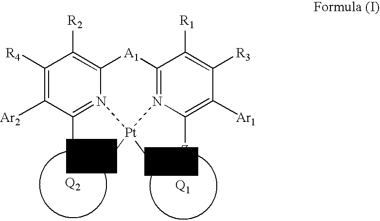
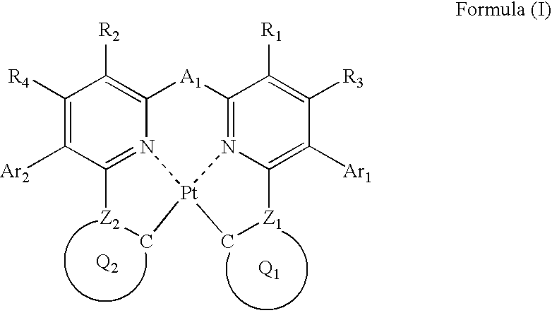
A compound is represented by the following formula (I):
wherein each of Ar1 and Ar2 independently represents an aromatic ring or an aromatic heterocyclic ring; each of R1, R2, R3 and R4 independently represents a hydrogen atom or a substituent; each of Z1 and Z2 independently represents a carbon atom or a nitrogen atom; each of ring Q1 containing a carbon atom and Z1, and ring Q2 containing a carbon atom and Z2 independently represents an aromatic ring or an aromatic heterocyclic ring; and A1 represents a single bond or a divalent linking group.

Description

BACKGROUND OF THE INVENTION[0001]1. Field of the Invention[0002]The present invention relates to a platinum complex compound useful as a light-emitting material, and an organic electroluminescence device (hereinafter also referred to as “an organic EL device) using the same.[0003]2. Description of the Related Art[0004]Organic electroluminescent devices are capable of obtaining emission of high luminance by low voltage driving, and actively researched and developed in recent years. An organic EL device generally consists of a pair of electrodes with an organic compound layer including a light-emitting layer, and electrons injected from the cathode and holes injected from the anode are recombined in the light-emitting layer, and generated energy of exciton is used for emission.[0005]The increase in efficiency of the devices has been advanced by the use of phosphorescent materials. Iridium complexes and platinum complexes are known as the phosphorescent materials, and a platinum comple...

Claims


Application Information

Patent Timeline
Patent Type & Authority Applications(United States)
IPC IPC(8): H01J1/63C07D213/02
CPCC07F15/0086C09K11/025C09K11/06H10K85/346H10K85/6572H10K50/11H10K2101/10C09K2211/1007C09K2211/1029C09K2211/1044C09K2211/185
Inventor KINOSHITA, IKUOMURAKAMI, TAKESHIIGARASHI, TATSUYA
Owner UDC IRELAND
Why Eureka
Try Eureka