
Method of biomass gasification

a biomass and gasification technology, applied in the field of biofuels, can solve the problems of large amount of energy required for drying biomass, many difficulties encountered, and many operational difficulties of the process, and achieve the effect of efficient gasification of biomass, especially

Inactive Publication Date: 2009-06-25
GENERAL ELECTRIC CO
View PDF10 Cites 31 Cited by
  • Summary
  • Abstract
  • Description
  • Claims
  • Application Information

AI Technical Summary

Benefits of technology

[0011]Thus, there is a need to develop new methods for efficiently gasifying biom

Problems solved by technology

Although gasification of biomass is a desired option, there are many difficulties encountered, due to the inherent nature of biomass.
Moreover, there are operational difficulties associated with the process.
As an example, due to the higher moisture content often present in biomass, a considerable amount of energy is required for drying the biomass.
The tar deposits create the need for frequent maintenance, and may also reduce the operating life of the gasification equipment.
The carryover of tar can deposit on and block filters, pipes, valves and turbochargers, leading to a decrease in performance.
In some instances, elaborate cleaning systems are required to address these problems.
However pressurized biomass gasifiers have their own set of problems.
One significant problem relates to the feeding of the biomass into the gasifier.
The characteristics of biomass, such as low density, varying particle size, and varying moisture content, lead to problems like clumping and interlocking of particles of different sizes.
Many practical difficulties have been faced in maintaining such feeding systems at high pressures.
Lock hopper systems do not have large turndown capability, and require the use of a considerable quantity of inert pressurizing gas for the lock hoppers or piston feeders.
However, water slurries involve energy penalties of evaporating the water in the gasifier.
However, if a water slurry is used for feeding biomass feedstock to a pressurized biomass gasifier, it may not sustain the gasification, due to the lower energy content of biomass feedstock.

Method used


Image

  • Method of biomass gasification
  • Method of biomass gasification

Examples


Embodiment Construction

[0017]As discussed in detail below, embodiments of the present invention describe a method for biomass gasification that allows for pressurized operation, with reduced tar formation.

[0018]Approximating language, as used herein throughout the specification and claims, may be applied to modify any quantitative representation that could permissibly vary without resulting in a change in the basic function to which it is related. Accordingly, a value modified by a term or terms, such as “about”, is not limited to the precise value specified. In some instances, the approximating language may correspond to the precision of an instrument for measuring the value.

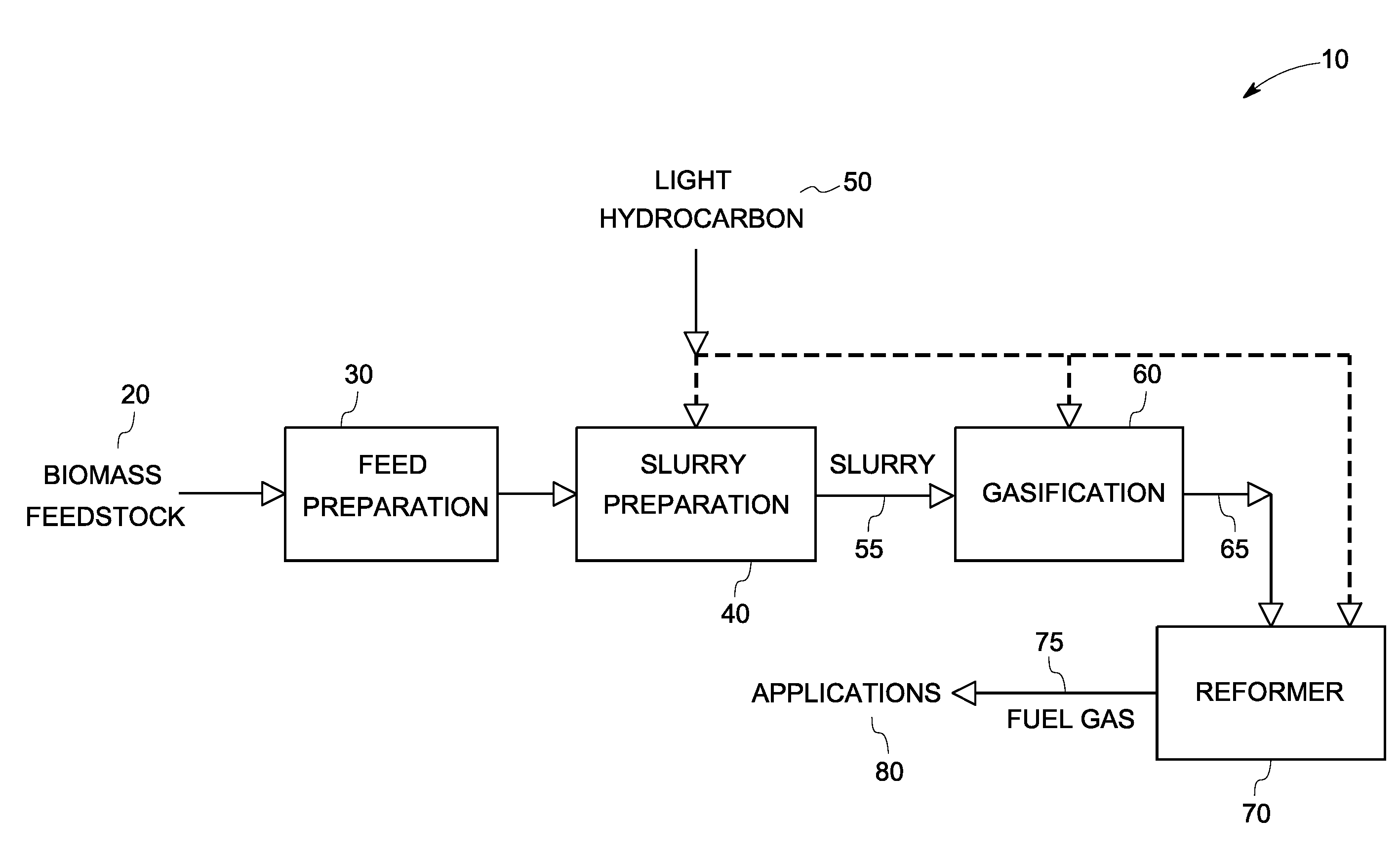
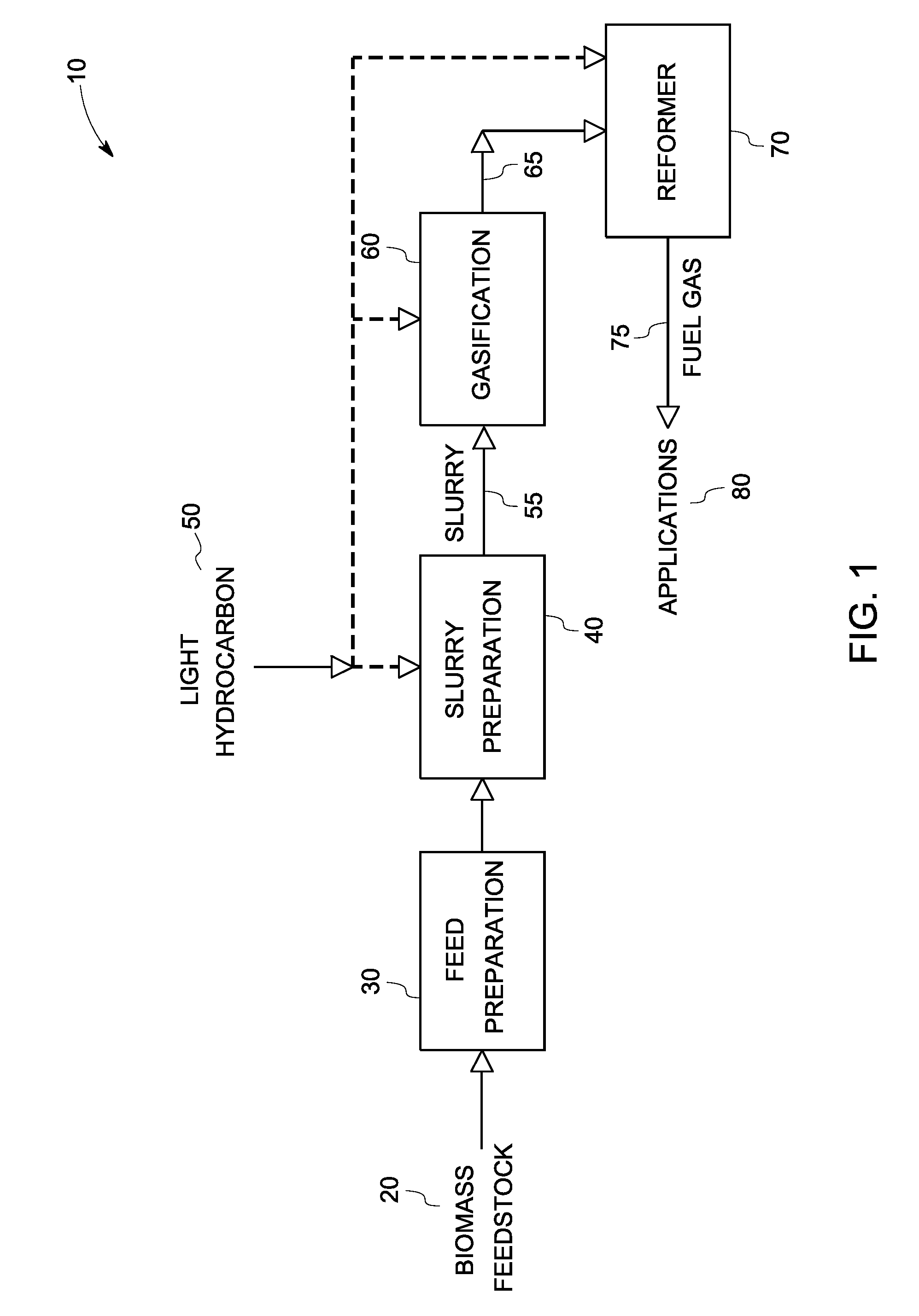
[0019]Various steps in the process are represented in FIG. 1. The method of biomass gasification is generally shown as 10. Biomass feedstock 20 undergoes a feed preparation step 30, where it undergoes preprocessing. Step 30 may be an optional step in some embodiments. The pre-processed biomass feedstock 20 is then mixed with a light ...


PUM


Abstract

A method for the gasification of biomass, wherein the biomass feedstock is combined with a light hydrocarbon composition to form a slurry; followed by feeding the slurry to a gasifier to produce a fuel gas. In another embodiment, a method for the gasification of biomass is described. The method includes the steps of combining a biomass feedstock with water to form a slurry; feeding the slurry to a gasifier to produce a fuel gas; and injecting a light hydrocarbon into the gasifier, to generate gasification temperatures greater than about 900° C., by partial or complete combustion of the light hydrocarbon. In some other embodiments, the biomass gasifier product gas is coupled to a reformer, wherein a light hydrocarbon is injected to generate high temperatures.

Description

BACKGROUND[0001]This invention generally relates to bio-fuels, and in particular to a method of carrying out biomass gasification.[0002]Biomass is receiving increased attention as a renewable energy source, in this era of emphasis on energy security and increasing environmental concerns.[0003]Multiple ways of utilization of biomass are being tried. Traditionally, the most common method of using the biomass has been to burn it, to provide heat energy. This heat energy is then used directly, or used to produce steam.[0004]It has been demonstrated that gasification of biomass is a better option than burning it. Gasification produces a clean burning gas that can be easily utilized. The product gas can be used as a feedstock for production of value added fuels and chemicals. The burning of this gas in internal combustion engines or turbines offers higher efficiencies, as compared to steam devices.[0005]Historically, gasification technology was used to convert coal into a combustible gas....

Claims


Application Information

Patent Timeline
IPC IPC(8): C10J3/00
CPCC10J3/463C10J3/466C10J2300/0903C10J2300/0916C10K3/04C10K3/003C10J3/721C10K3/005C10J2300/0989Y02P20/145
Inventor DELUGA, GREGG ANTHONYZAMANSKY, VLADIMIRKULKARNI, PARAG PRAKASH
Owner GENERAL ELECTRIC CO
Learn More