System and Method of Providing Power Using Switching Circuits

a switching circuit and power supply technology, applied in the direction of logic circuit coupling/interface arrangement, constant-current supply dc circuit, ac network voltage adjustment, etc., can solve the problems of power supply buckling, power supply buckling and possible metal interconnection electromigration, and increase the risk of power supply failure, so as to reduce the surge current associated with charging the power grid, reduce the surge current, and reduce the effect of surge curren

Active Publication Date: 2009-06-25
QUALCOMM INC
View PDF6 Cites 13 Cited by
  • Summary
  • Abstract
  • Description
  • Claims
  • Application Information

AI Technical Summary

Benefits of technology

[0008]One particular advantage provided by embodiments of the power switching circuit is provided in that a surge current associated with charging of a power grid is reduced.
[0009]Another particular advantage is that, by turning on a first set of transistors (trickle devices) and then turning on a second set of transistors (flood devices), a power grid can be pre-charged to a voltage level that is less than a supply voltage level and the power grid is then ramped to the supply voltage level, reducing a surge current due to a capacitance associated with the power grid. In a particular example, the power grid may be pre-charged to approximately half of the supply voltage level
[0010]Yet another advantage is that low power circuitry, which is coupled to a power grid of a circuit, i

Problems solved by technology

In some circuits, leakage currents represent a significant drain on power resources.
While head switches or foot switches are sometimes used to reduce leakage currents, the activation and deactivation of such switches can introduce large current spikes.
Such a large inst

Method used


Image

  • System and Method of Providing Power Using Switching Circuits
  • System and Method of Providing Power Using Switching Circuits
  • System and Method of Providing Power Using Switching Circuits

Examples


Embodiment Construction

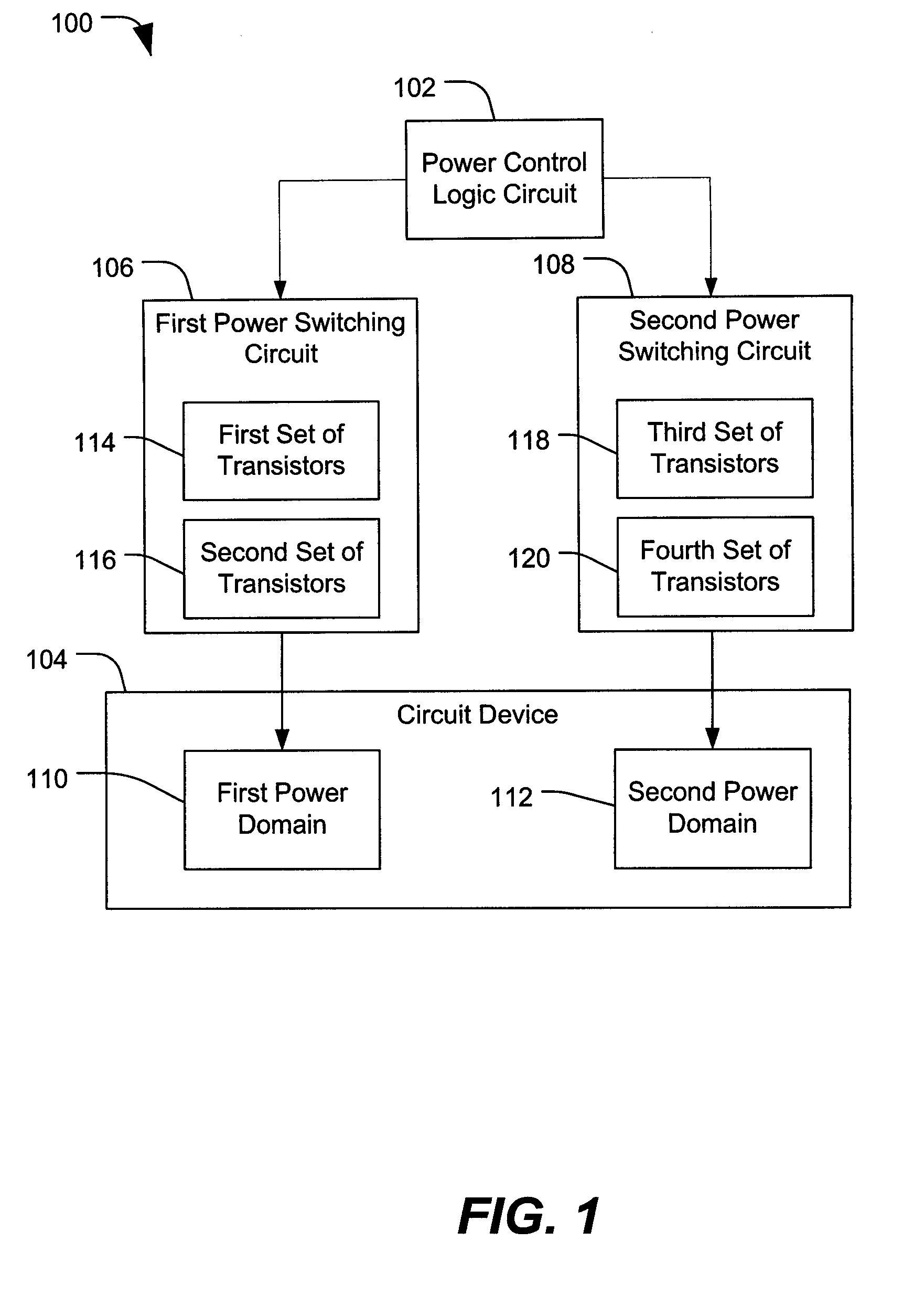
[0022]FIG. 1 is a block diagram of a particular illustrative embodiment of a circuit device 100 to provide power using switching circuits. The circuit device 100 includes a power control logic circuit 102 that is responsive to a circuit device 104 via a first power switching circuit 106 and a second power switching circuit 108. The power control logic circuit 102 is adapted to selectively activate the first power switching circuit 106 and the second power switching circuit 108. The circuit device 104 includes a first power domain 110 that is responsive to the first power switching circuit 106 and a second power domain 112 that is responsive to the second power switching circuit 108. The first power switching circuit 106 includes a first set of transistors 114 and a second set of transistors 116. The second power switching circuit 108 includes a third set of transistors 118 and a fourth set of transistors 120. The first, second, third, and fourth sets of transistors 114, 116, 118, an...


PUM


Abstract

In a particular illustrative embodiment, a system is disclosed that includes a first power domain that is responsive to a first power switching circuit and a second power domain that is responsive to a second power switching circuit. The system also includes a logic circuit adapted to selectively activate the first power switching circuit and the second power switching circuit. At least one of the first power switching circuit and the second power switching circuit includes a first set of transistors adapted for activation during a first power up stage and a second set of transistors adapted for activation during a second power up stage after at least one of the first set of transistors are activated.

Description

FIELD[0001]The present disclosure is generally related to a system and method of providing power using switching circuits.Description of Related Art[0002]In general, integrated circuit devices can include multiple circuit components, which are powered from a power source. Conventionally, mobile telephones and other portable computing devices include integrated circuits, such as processors, memory circuits, and other types of circuits, which rely on a portable power source, such as a battery. Accordingly, it is desirable to reduce overall power consumption in order to extend the battery life of the devices.[0003]In some circuits, leakage currents represent a significant drain on power resources. While head switches or foot switches are sometimes used to reduce leakage currents, the activation and deactivation of such switches can introduce large current spikes. In particular, a power grid of a circuit device may represent a large capacitance (C). When a head switch or foot switch is ...

Claims


Application Information

Patent Timeline
IPC IPC(8): H02J1/00H02J3/14
CPCH03K19/017581H03K19/00361
Inventor RAO, HARICHEN, NANCHABA, RITU
Owner QUALCOMM INC
Why Eureka
Try Eureka