Laser light source device and image display apparatus

a laser light source and image display technology, applied in the direction of instruments, optical fibres with polarisation, cladding optical fibres, etc., can solve the problems of damage to the excitation light source, unstable oscillation operation of the laser resonator, and deterioration of the fiber, so as to prevent the fiber from deterioration, broader color reproduction range, and wide absorption spectrum

Active Publication Date: 2009-06-25
PANASONIC CORP
View PDF7 Cites 11 Cited by
  • Summary
  • Abstract
  • Description
  • Claims
  • Application Information

AI Technical Summary

Benefits of technology

[0029]According to the present invention, residual excitation light in the double-clad fiber into which the excitation light has been allowed to fall from the laser light source is prevented from exiting to the single-mode fiber. This makes it possible to prevent the fiber deterioration which is likely to be caused when light of a high output is generated. Accordingly, an image display apparatus which is provided with a laser light source device according to the present invention can have a color reproduction range wider than apparatuses provided with the conventional solid state laser.
[0030]As excitation light, further, this device can use light having a band of 915 nm, which provide a broader absorption spectrum for a rare-earth fiber. Hence, there is no need to control the temperature for excitation precisely, which can thus eliminate a Peltier element and reduce the power consumption.
[0031]Moreover, a laser light source device according to the present invention has a high efficiency to thereby decrease the power consumption further.

Problems solved by technology

Particularly, YLF is a fluoride crystal and hard to produce.
As mentioned with reference to Patent Document 1, a part of oscillation light turns into undesirable return light, which may damage an excitation light source.
This makes the oscillation operation of a laser resonator unstable.
This causes deterioration of the fiber.
In other words, at a wavelength of 1050 nm or 1030 nm at which the fiber has a great loss, an output to be generated is inevitably limited.
However, at a wavelength of 1060 nm, 1050 nm or the like where green color can be produced by a wavelength conversion, the problems have been known that the loss which is caused by absorption of a fiber increases as the length of a rare-earth-added double-clad polarization maintaining fiber increases, the oscillation becomes unstable, the oscillation cannot be performed at a desired wavelength.
Therefore, the intensity of excitation light is obviously determined to keep a fiber from being overheated, thus limiting the maximum output.
Hence, it has been conventionally difficult to attain both the temperature stabilization of a fiber laser device and generation of light having a linear polarization, 6 W or more, and 1075 nm or less using a fiber laser device.Patent Document 1: Japanese Patent No. 3012034Non-patent Document 1: Japanese Journal of Applied Physics Vol. 43, No. 8B, 2004, pp.

Method used


Image

  • Laser light source device and image display apparatus
  • Laser light source device and image display apparatus
  • Laser light source device and image display apparatus

Examples


first embodiment

[0052]A first embodiment of the present invention offers a residual excitation light radiating-and-absorbing mechanism utilizing a loss which is caused due to a curvature of a fiber.

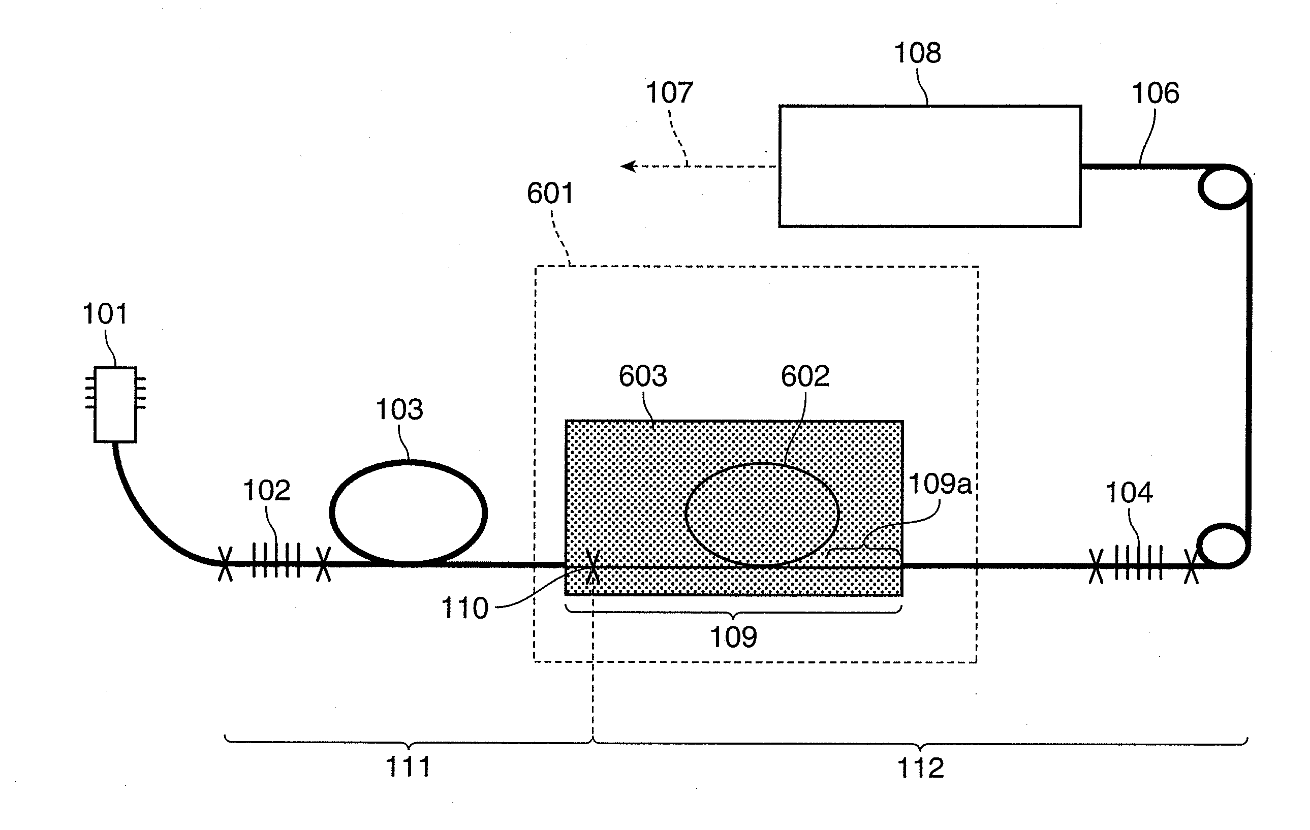
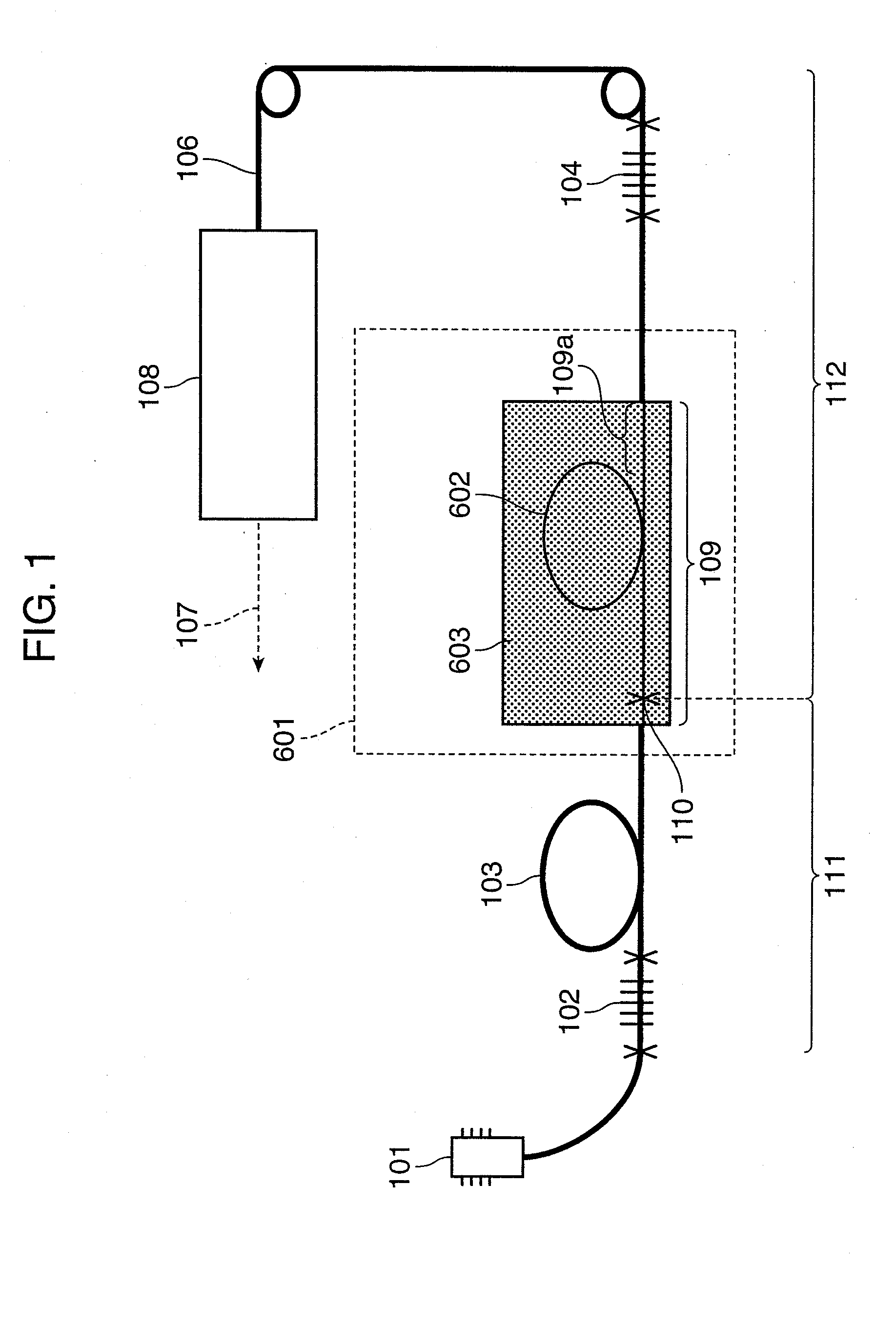
[0053]FIG. 1 shows a configuration of a laser light source device according to the first embodiment. In FIG. 1, the laser light source device of this embodiment includes: a pumping LD (Laser Diode) 101; a fiber grating 102; a Yb-doped double-clad polarization maintaining fiber 103; a fiber grating 104; and a residual excitation light radiating-and-absorbing mechanism (pumping light radiating-and-absorbing mechanism) 601. The laser light source device according to this embodiment is connected to a second-harmonic generation (SHG) module 108 via an oscillation light propagation fiber 106.

[0054]The pumping LD 101 excites the double-clad polarization maintaining fiber 103 (in this embodiment, fiber length: 10 m) doped with Yb as a rare earth on a core part of a double-clad polarization maintaining fiber 111....

second embodiment

[0068]Next, a description will be given about a configuration of a laser light source device according to a second embodiment of the present invention. In this embodiment, a fiber strand is placed in a high refractive material.

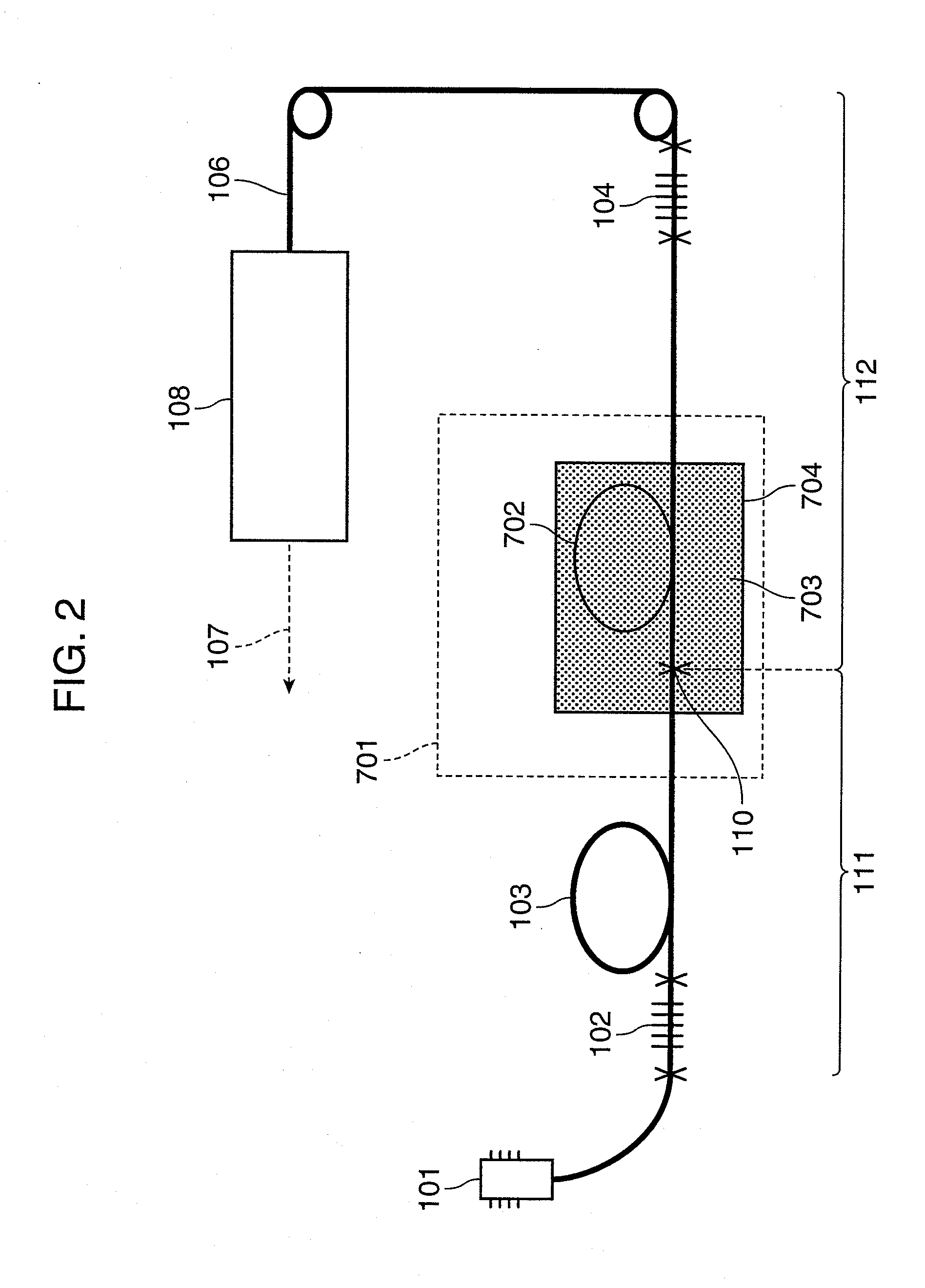
[0069]FIG. 2 shows a configuration of a laser light source device according to the second embodiment. In the above described first embodiment, the coil-shaped portion 602 is placed in air having a refractive index of 1, and the coat removed portion 109 including the coil-shaped portion 602 of the single-mode polarization maintaining fiber 112 functions as a multi-mode fiber for excitation light. Then, the bending curvature of the coil-shaped portion 602 is made greater to thereby radiate unnecessary excitation light.

[0070]However, the difference in refractive index between the clad of the single-mode polarization maintaining fiber 112 and the air is approximately 1.4. To increase the radiation efficiency of excitation light further, accordingly, the refractive...

third embodiment

[0080]A third embodiment of the present invention provides away where a lens system is provided between a rare-earth-doped double-clad polarization maintaining fiber and a single-mode polarization maintaining fiber to thereby allow a laser light to go out into space, and then, excitation light is decreased utilizing a difference in convergence beam diameter between excitation light and oscillation light.

[0081]FIG. 3 shows a configuration of a wavelength-conversion light source device provided with a fiber laser according to the third embodiment. In FIG. 3, the laser light source device according to this embodiment includes: a pumping LD 101; a fiber grating 102; a Yb-doped double-clad polarization maintaining fiber 103; a fiber grating 104; and an excitation light absorbing mechanism 801. The laser light source device according to this embodiment is connected to a SHG (second-harmonic generation) module 108 via an oscillation light propagation fiber 106. A polarizer 105 is provided ...


PUM


Abstract

There has been a problem that pumping light leaks from a part having a coating at the joint of a double-clad fiber added with a rare earth and a general single-mode fiber, and heat is generated partly from the fiber by this energy thus causing deterioration of the fiber. Deterioration of a fiber due to residual excitation light can be prevented by preventing residual excitation light in a double-clad fiber from exiting to a single-mode fiber, and the reliability is enhanced. Output of oscillation light can be increased because output of excitation light is not limited. Furthermore, a laser display having a high color reproducibility can be achieved by employing a light source combining a fiber laser light source and a wavelength conversion module.

Description

TECHNICAL FIELD[0001]The present invention relates to a laser light source device which is capable of attaining a stable high output, and an image display apparatus provided with this laser light source device.BACKGROUND ART[0002]In recent years, a fiber laser light source has received much attention as a near infrared laser light source, instead of a conventional solid state laser light source. This is because the fiber laser light source has a high oscillation efficiency and an excellent beam quality, and further, can be cooled with air and has a simple structure.[0003]FIG. 13 is a schematic diagram showing a configuration of a typical fiber laser light source. Laser light emitted from an exciting (pumping) LD (laser diode) 101 is incident upon a rare-earth-doped clad pumping fiber 103 as a laser medium. Then, it is resonated in a laser resonator made up of fiber gratings 102 and 104 as a reflecting mirror and thereby oscillated.[0004]A polarizer 105 is inserted for unifying the p...

Claims


Application Information

Patent Timeline
Patent Type & Authority Applications(United States)
IPC IPC(8): H01S3/067
CPCG02B6/024G02B6/036G02B6/262H01S3/09415H01S3/06712H01S3/0675H01S3/094015G03B21/00G03B21/005
Inventor FURUYA, HIROYUKIMIZUUCHI, KIMINORIYAMAMOTO, KAZUHISA
Owner PANASONIC CORP
Why Eureka
Try Eureka