Reduced liquid discharge in wet flue gas desulfurization

a technology of wet flue gas and desulfurization, which is applied in the direction of separation processes, machines/engines, lighting and heating apparatus, etc., can solve the problems of high cost of wastewater treatment facilities used in conjunction with wfgd systems, negative impact on so/sub>x removal, and corrosion and other damage in the wfgd system. , to achieve the effect of reducing the amount of purge liquid

Active Publication Date: 2009-06-25
GENERAL ELECTRIC TECH GMBH
View PDF2 Cites 69 Cited by
  • Summary
  • Abstract
  • Description
  • Claims
  • Application Information

AI Technical Summary

Benefits of technology

[0011]Another aspect of the present invention relates to a method of reusing an amount of purge liquid in a flue gas stream treatment system. The method includes the steps of: removing fly ash from a flue gas stream and transporting the fly ash to a solids mixer; combining the fly ash with a purge liquid which has been directed from a wet scrubber to the solids mixer; forming a moistened fly ash from the fly ash and purge liquid; and injecting the moistened fly ash mixture into the flue gas stream, thereby reducing the amount of purge liquid sent to a wastewater treatment plant.

Problems solved by technology

This buildup can cause corrosion and other damage in the WFGD system, and can negatively affect SOx removal.
Typically, wastewater treatment facilities used in conjunction with WFGD systems are expensive.
The design and supply cost of such a facility can exceed the cost of other systems used in connection with the WFGD plant.
The cost of the wastewater treatment facility is even more pronounced when organic acids are used in the WFGD system.
In addition to operating expense, the wastewater treatment facilities require large portions of land, additional equipment, and several buildings.
The capital and operating costs of a wastewater facility are dramatically increased when a biological reactor is required to remove organic acids or other constituents that may be used in or captured by the WFGD system.

Method used


Image

  • Reduced liquid discharge in wet flue gas desulfurization
  • Reduced liquid discharge in wet flue gas desulfurization
  • Reduced liquid discharge in wet flue gas desulfurization

Examples


Embodiment Construction

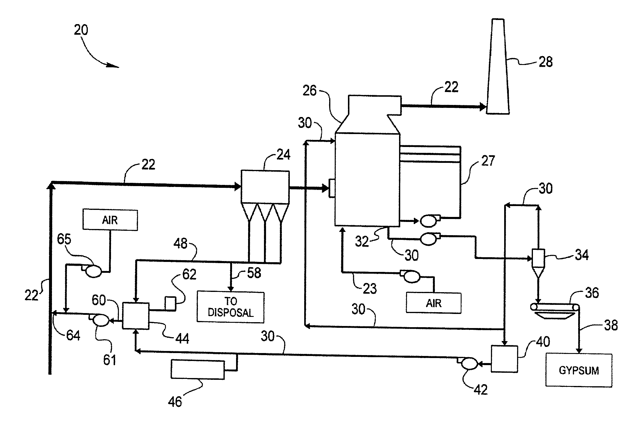
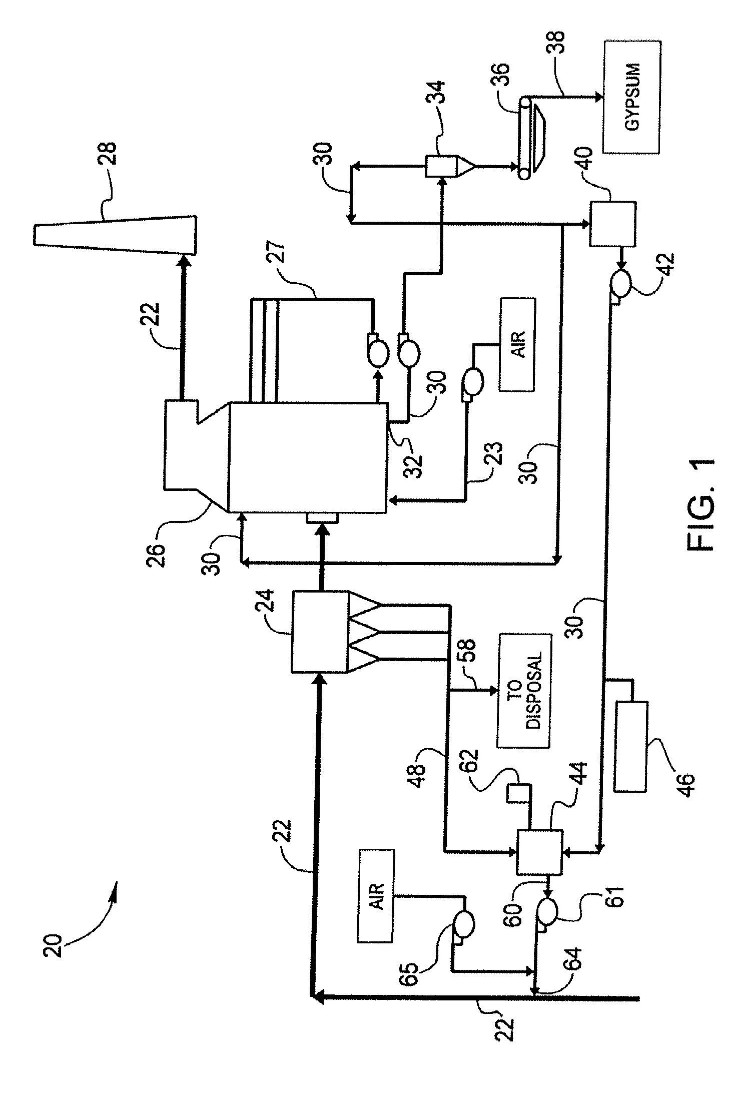
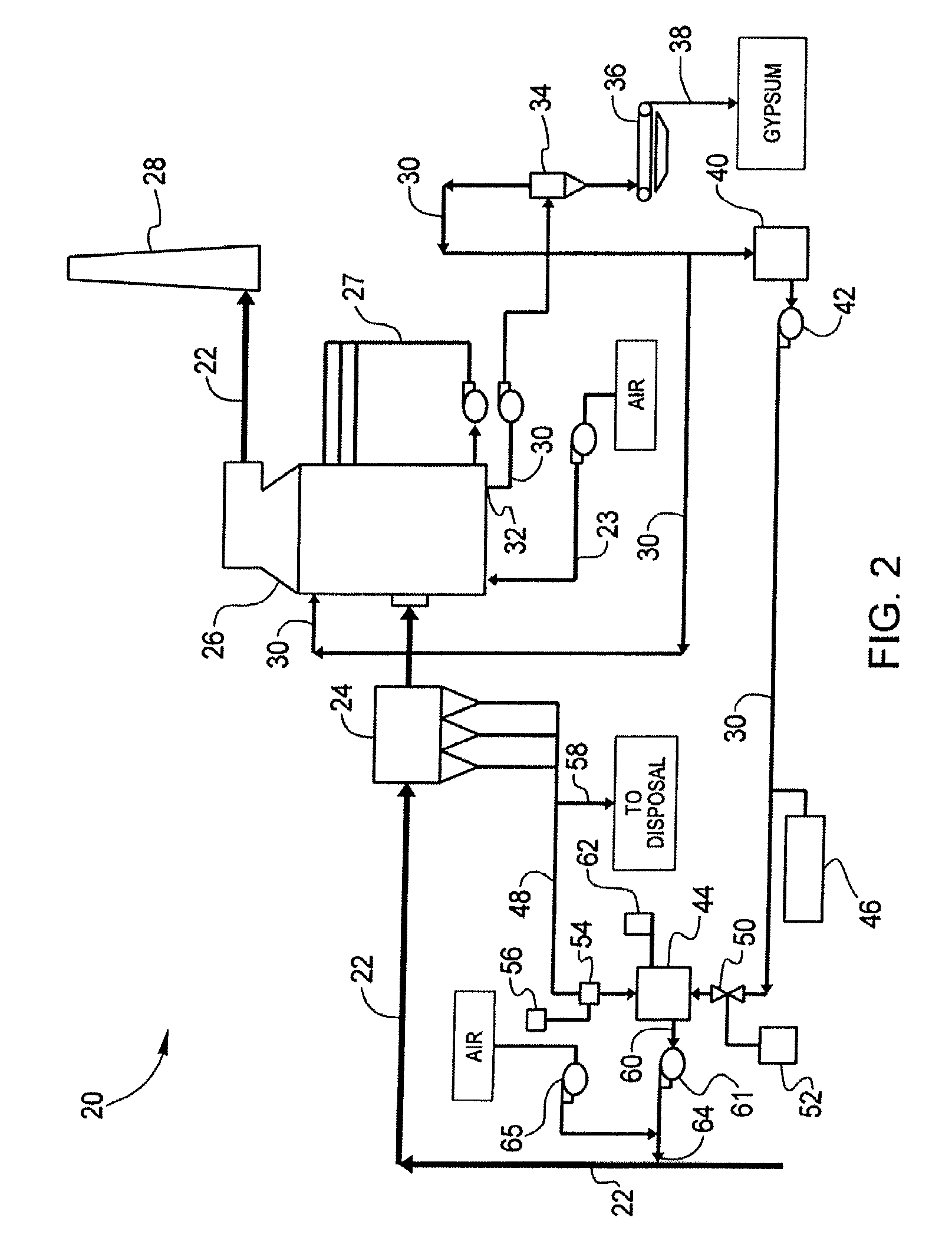
[0023]The processes and systems described herein are typically used in coal-combustion systems; however it is foreseeable to use such processes and systems in waste-to-energy plants, and other facilities that produce a flue gas stream.

[0024]Flue gas streams contain, among other things: ash particles, noxious substances and other impurities that are considered to be environmental contaminants. Prior to being emitted into the atmosphere via a smoke stack (“stack”), the flue gas stream undergoes a cleansing or purification process. In coal combustion, this purification process is normally a desulfurization system.

[0025]Now referring to FIGS. 1-3, in which like numerals correspond to like parts, in the WFGD system 20, a flue gas stream 22 leaves a boiler and travels to a particle collector 24. Particle collector 24 may be a bag house, an electrostatic precipitator, a venturi-type scrubber or any similar apparatus that can facilitate the removal of particles from flue gas stream 22.

[0026...


PUM

PropertyMeasurementUnit
alkalineaaaaaaaaaa
total weightaaaaaaaaaa
corrosionaaaaaaaaaa

Abstract

One aspect of the invention relates to a method for removing contaminants from a flue gas stream (22). The method includes: removing fly ash from a flue gas stream (22) utilizing a particle collector (24); contacting the flue gas stream with an alkaline reagent in a wet scrubber (26); discharging a purge liquid (30) from the wet scrubber (26); and, combining at least a portion of the purge liquid with at least a portion of fly ash circulating within a dry circulating fluid bed scrubber (48) to form moistened fly ash (60).

Description

CLAIM OF PRIORITY[0001]This application is a continuation-in-part of co-pending U.S. utility application entitled, “REDUCED LIQUID DISCHARGE IN WET FLUE GAS DESULFURIZATION,” having Ser. No. 11 / 486,705, filed Jul. 13, 2006, attorney docket number W03-036-0, the disclosure of which is entirely incorporated herein by reference.FIELD OF THE INVENTION[0002]This invention relates to a wet flue gas desulfurization process. More particularly, this invention relates to reducing the amount of purge liquid discharged to a wastewater treatment system from a wet flue gas desulfurization system.DESCRIPTION OF THE RELATED ART[0003]Federal, state and even some local governments have laws regulating the emission of particulates, gases and other contaminants present in gas produced in coal combustion. To comply with these laws, industries must implement systems that reduce or eliminate emissions of particulates and / or gases that have been deemed harmful to the environment.[0004]Several technologies ...

Claims


Application Information

Patent Timeline
Patent Type & Authority Applications(United States)
IPC IPC(8): B01D53/46B03C3/00B01D50/00
CPCB01D53/501B01D53/508B01D2257/2045B01D53/96B01D53/68
Inventor BARGER, KELLY L.DOULE, GREGG R.VARNER, MICHAEL G.
Owner GENERAL ELECTRIC TECH GMBH
Why Eureka
Try Eureka