GPS Baseband Architecture

a baseband and positioning system technology, applied in the direction of instruments, digital transmission, transmission, etc., can solve the problems of increasing power consumption and the required layout area inside the chip, affecting the use of affecting the general position determination. , to achieve the effect of improving the use layout area and power consumption

Active Publication Date: 2009-07-02
SYNOPSYS INC
View PDF5 Cites 9 Cited by
  • Summary
  • Abstract
  • Description
  • Claims
  • Application Information

AI Technical Summary

Benefits of technology

[0010]The foregoing needs are met by a GPS baseband architecture according to embodiments of the present invention. In one such embodiment of the present invention that improves used layout area and power consumption inside the chip where the architecture is implemented, while providing desired flexibility, the GPS baseband architecture includes at least a poly-phase filter, a programmable gain amplifier (PGA), an analog-to-digital converter (ADC) and a digital analog gain control (AGC) machine.

Problems solved by technology

While the C / A code is always available, to prevent spoofing or other man-made data corruption, the P code may be encrypted, and may not be available for general position determination.
Such high order filters increasing the power consumption and the required layout area inside the chip.
The GPS baseband architecture normally uses a high order filter after the mixer, increasing notably the power consumption and the required layout area inside the chip.

Method used


Image

  • GPS Baseband Architecture
  • GPS Baseband Architecture
  • GPS Baseband Architecture

Examples


Embodiment Construction

[0025]The present invention provides a GPS baseband architecture that improves used layout area and power consumption inside the chip, while providing desired flexibility. In the detailed description of the invention that follows, references to “one embodiment”, “an embodiment”, “an example embodiment”, etc., indicate that the embodiment described may include a particular feature, structure, or characteristic, but every embodiment may not necessarily include the particular feature, structure, or characteristic. Moreover, such phrases are not necessarily referring to the same embodiment. Further, when a particular feature, structure, or characteristic is described in connection with an embodiment, it is submitted that it is within the knowledge of one skilled in the art to effect such feature, structure, or characteristic in connection with other embodiments whether or not explicitly described.

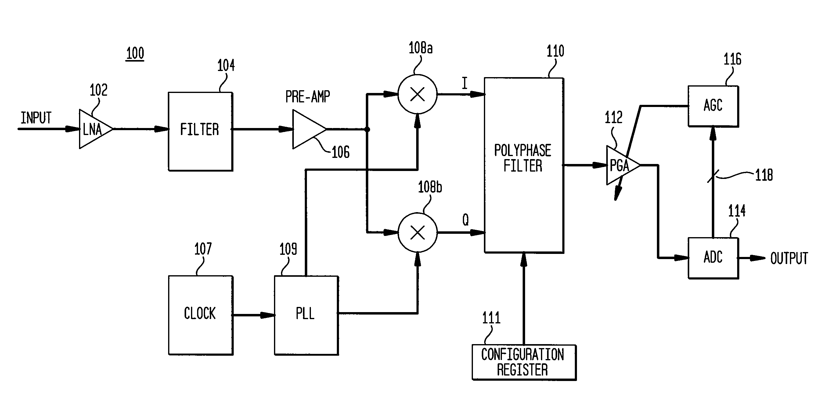
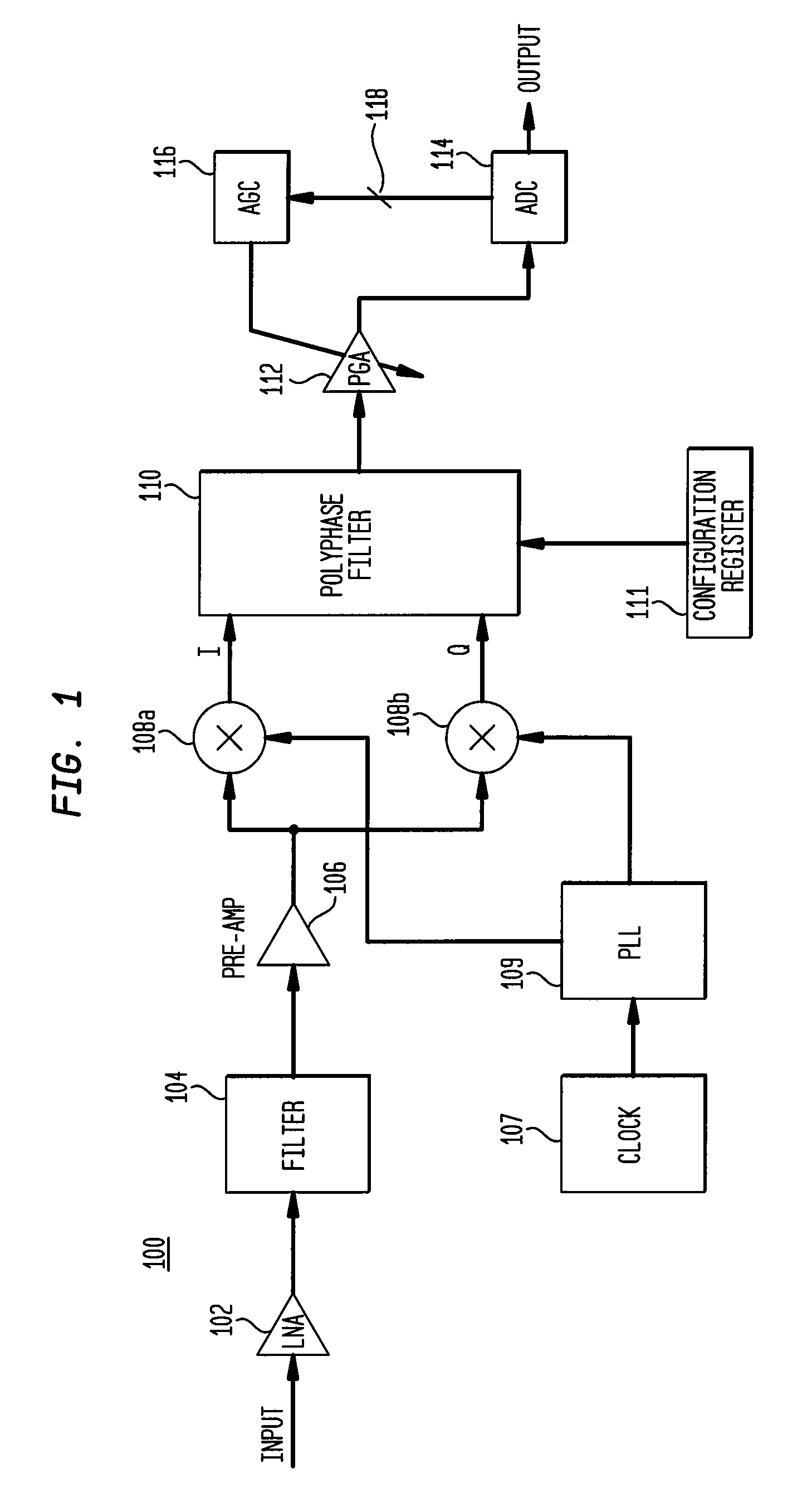
[0026]FIG. 1 is a schematic diagram of a GPS baseband architecture 100 according to an embo...


PUM


Abstract

A GPS baseband architecture provides flexibility and power consumption and chip area usage advantages. The GPS baseband architecture includes a first stage having a preamplifier coupled to a low noise amplifier, which is coupled to a mixer. A PLL provides the mixer with a frequency to convert a signal to a higher intermediate (IF) frequency. The output of the mixer is fed to a poly-phase filter. The output of the poly-phase filter is fed to a programmable gain amplifier (PGA), whose output is fed to an analog-to-digital converter (ADC) to produce an output GPS signal. A saturation bit of the ADC is used to control the PGA through a digital amplifier gain control (AGC) circuit.

Description

FIELD OF THE INVENTION[0001]Embodiments of the present invention relate to a GPS (Global Positioning System) baseband architecture based on a lower order poly-phase filter followed by one PGA (Programmable Gain Amplifier) and a simpler AGC (Amplifier Gain Control) machine where the control is based on a calculation of the average time the ADC is saturated.BACKGROUND OF THE INVENTION[0002]Knowledge of one's position is required for numerous endeavors in modern life. By way of example, surveyors require precise positioning for land surveys and construction projects. Shipping companies implement tracking devices in containers requiring position information to monitor their locations. Numerous types of service companies use position information to track the locations of their service personnel as they make various service calls to ensure they're not deviating from their assignments. Drivers use knowledge of their position to obtain driving directions from one point to another and to det...

Claims


Application Information

Patent Timeline
Patent Type & Authority Applications(United States)
IPC IPC(8): G01S1/00G01S19/11
CPCG01S19/33G01S19/37G01S19/36
Inventor REIS, RICARDO DOS SANTOS
Owner SYNOPSYS INC
Why Eureka
Try Eureka