
Refractory mortar cured material

Active Publication Date: 2009-07-02
NGK INSULATORS LTD +1
View PDF4 Cites 5 Cited by
  • Summary
  • Abstract
  • Description
  • Claims
  • Application Information

AI Technical Summary

Benefits of technology

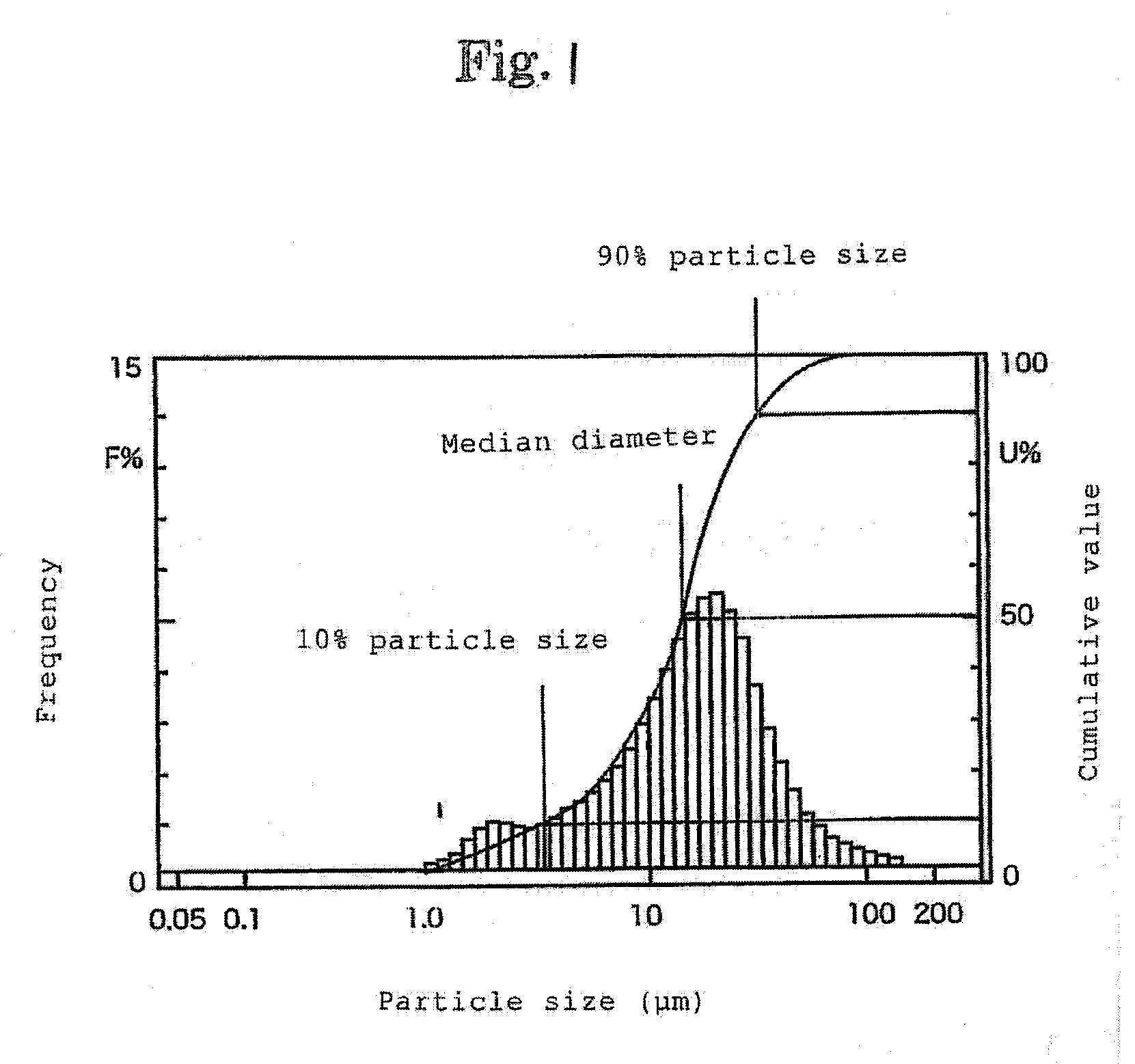
[0010]According to the invention, the average particle size of ceramic particles for composing the refractory mortar cured material is 10 to 50 μm, the difference of 90% particle size and 10% particle size is 10 μm or more to 60 μm or less, and the particle size distribution of ceramic particles is controlled. Moreover, the average pore size of the formed refractory mortar cured material is 5 to 25 μm, and the width of pore size distribution is controlled at 20 μm or more to 80 μm or less. As a result, fluctuations of pore size of refractory mortar cured material are suppressed, and propagation of cracks can be effectively suppressed, and the refractory mortar cured material excellent in durability and reliability is obtained. The particle size and its distribution of refractory mortar cured material may be obtained by image analysis using commercial analysis software.

Problems solved by technology

In such a case, since moisture is absorbed in the base material when the refractory mortar is applied on the base material surface or joint portions, a local shrinkage difference occurs in the refractory mortar cured material, and fine cracks may be generated.
Even by this technology in patent document 1, it is insufficient in depression of cracks occurring in initial period of forming the ceramic material or cracks occurring by heating after coating process, and it is not satisfactory from the viewpoint of thermal impact resistance.
Generally, cracks are caused when the ceramic material is exposed to thermal stress during drying or heating process, but propagation of cracks may be blocked by pores existing in the texture.
However, in the ceramic material in patent document 1, since cracks are not uniform in size and are localized, it is estimated that cracks may not be suppressed sufficiently.

Method used


Image

  • Refractory mortar cured material

Examples


examples

[0022]Examples of the invention are described below.

[0023]Examples of refractory mortar shown in Table 1 were prepared, and the mortar was applied on the surface of ceramic refractory material of cordierite, and the refractory mortar cured material was formed, and the pore size was measured by image analysis. The characteristics were measured in these refractory mortar cured materials, and the results are shown in Table 1. The crack initiation temperature was evaluated by drying refractory mortar cured material pieces measuring 60×50×1 mm, at temperature of 40 to 110° C. for 8 hours or more, and each sample was taken out to room temperature from the environments which are heated to various temperatures, and the presence or absence of crack was visually checked, and the temperature at which a crack was observed first was determined as crack initiation temperature. Favorable results were obtained in the examples, and the crack initiation temperature was over 500° C.

[0024]By contrast, ...


PUM

PropertyMeasurementUnit
Fractionaaaaaaaaaa
Fractionaaaaaaaaaa
Pore size distributionaaaaaaaaaa

Abstract

The refractory mortar cured material of the invention formed in the surface or joint portions of a ceramic refractory material such as fire bricks used in the lining of melting furnace or firing furnace used at high temperature is composed by kneading ceramic particles with an inorganic binder having silanol group together with water, and forming the kneaded mortar on the surface of a ceramic base material. The average particle size of ceramic particles in the refractory mortar is 10 to 50 μm, the difference of 90% particle size and 10% particle size is 10 μm or more to 60 μm or less, the average pore size of the refractory mortar cured material is 5 to 25 μm, and the width of pore size distribution is 20 to 80 μm, so that the cracks may be suppressed. More preferably, the bulk density is 0.9 to 1.5 g / cm3.

Description

BACKGROUND OF THE INVENTION[0001]1. Field of the Invention[0002]The present invention relates to a refractory mortar cured material applied on surface or joint portions of ceramic refractory materials such as fire bricks used in linings of melting furnace or firing furnace used at high temperature.[0003]2. Description of the Related Art[0004]On surface or joint portions of porous ceramic refractory material, refractory mortar cured materials are often formed for the purposes of enhancing the corrosion resistance or mechanical strength by isolating from the ambient atmosphere, adhering, and mending and the like. In such a case, since moisture is absorbed in the base material when the refractory mortar is applied on the base material surface or joint portions, a local shrinkage difference occurs in the refractory mortar cured material, and fine cracks may be generated. Besides, when the moisture is absorbed in the base material, the viscosity of the refractory mortar is raised, and th...

Claims


Application Information

Patent Timeline
IPC IPC(8): B32B3/26
CPCC04B28/24C04B35/195C04B35/66C04B38/0022C04B2111/00431C04B2235/3418C04B2235/3481C04B2235/349C04B2235/5208C04B38/0054C04B38/0067C04B14/041C04B14/10C04B14/46C04B14/042Y10T428/249979
Inventor KOMIYAMA, TSUNEOYAMAKAWA, OSAMUHONJO, TETSUHIROHIGUCHI, AKITO
Owner NGK INSULATORS LTD
Learn More