
Gait modulation system and method

a technology of gait and modulation system, applied in the field of gait modulation system and method, can solve the problems of reducing walking speed, affecting the normal functioning of hands or legs, and affecting the accuracy of gait modulation, so as to achieve the effect of precise and repeatable positioning of the layer

Active Publication Date: 2009-07-09
BIONESS NEUROMODULATION
View PDF66 Cites 68 Cited by
  • Summary
  • Abstract
  • Description
  • Claims
  • Application Information

AI Technical Summary

Benefits of technology

[0039]According to still further features in the described preferred embodiments, circumferentially disposed on the frame is at least one spring-loaded strip, the strip being radially spring-loaded towards a center of the frame, such that in donning the orthosis around the limb segment, the spring-loaded strip applies a pressure against the limb segment, such that the orthosis is self-retained in position on the limb segment while allowing for small adjustments to be made in positioning of the orthosis on the limb segment.
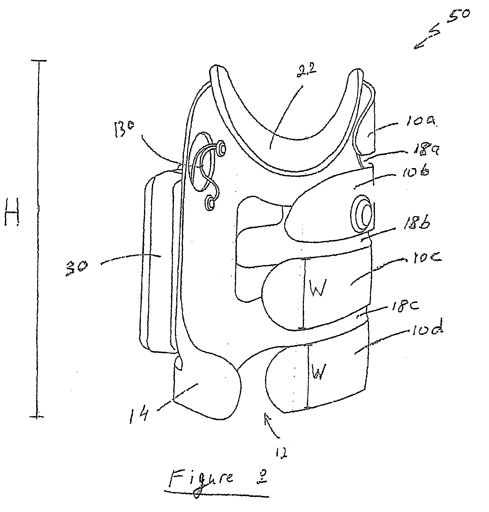
[0057]According to yet another aspect of the present invention there is provided an orthosis for providing electrical stimulation to a limb segment of a user, the orthosis including: (a) an at least semi-rigid frame configured to substantially envelop the limb segment, the frame having at least one first complementary mechanical fastener associated therewith; (b) at least one surface electrical stimulation electrode assembly associated with, and supported by the frame, the assembly having a surface stimulation electrode for contacting at least one stimulation point on the limb segment, the at least one surface electrode assembly having an electrode base for electrically associating, via the frame, with a stimulator unit for providing a stimulation signal to the surface electrode, the electrode base having a top face for receiving the stimulation electrode, the electrode base having a bottom face having at least one second complementary mechanical fastener, the second fastener being complementary to the first fastener, the first and second fasteners designed and configured for reversible attachment and reversible detachment, at a plurality of locations on the frame, thereby enabling the electrical stimulation electrode assembly to be adjustably and reversibly positioned on the frame.
[0060]According to still further features in the described preferred embodiments, the electrode base is loosely associated with the first conductive fastener by means of a flexible wire, thereby enabling the electrical stimulation electrode assembly to be adjustably and reversibly positioned on the frame in a plurality of positions, according to individual needs of the user.
[0063]According to yet another aspect of the present invention there is provided an orthosis for providing electrical stimulation to a limb segment of a user, the orthosis including: (a) a frame configured to substantially envelop a limb segment of a user, the frame being made of an at least semi-rigid material and associated with a first fastener at an inner face of the frame; (b) at least one electrical stimulation electrode assembly associated with, and supported by the frame, the stimulation electrode assembly for electrical association, via the frame, with a stimulator unit; (c) a soft, reversibly attachable and detachable layer having a second fastener complementary to the first fastener for reversible attachment and detachment of the layer from an inner face of the frame, the at least one electrical stimulation electrode assembly being associated with, and located on, an inner face of the layer such that, when the orthosis is donned on the limb segment, an electrical stimulation electrode of the electrode assembly is positioned so as to contact at least one stimulation point of a muscle of the user, the soft, reversibly attachable and detachable layer for providing the user with a comfortable interface between the frame and the limb segment during donning of the orthosis.
[0065]According to still further features in the described preferred embodiments, the layer further includes a snap connector for attaching the layer to the frame, the snap connector being complementary to a connector associated with the frame so as to provide a secure mechanical attachment to the frame, thereby ensuring exact and repeatable positioning of the layer, with respect to the frame.
[0066]According to still further features in the described preferred embodiments, the layer further includes a hollow snap connector, the hollow connector being complementary to a recess associated with the frame so as to provide a tight mechanical attachment to the frame, thereby ensuring exact and repeatable positioning of the layer, with respect to the frame.

Problems solved by technology

It is known that pathologies of the neuromuscular system due to disease or trauma to the central nervous system, such as stroke, spinal cord injury, head injury, cerebral palsy and multiple sclerosis, can impede proper limb functioning of the hands or legs.
Gait, the biomechanical description of walking, can suffer static and dynamic parameter variations due to neuromuscular impairments, which cause non-symmetrical walking, reduced walking speed and reduced walking stability.
These patients tend to have impaired stability, are prone to frequent falls, and their walking movements are unaesthetic and energy consuming.
These systems suffer from many drawbacks that prevent them from being widely used by potential patients.
When problems with arm movement or gait result from stroke or brain injury, they are often accompanied by hand impairment on the same side of the body as the limb on which the FES orthosis is donned.
Moreover, the posture of the plegic limb is often problematic, especially in cases where spasticity results in reduced voluntary movements and also in a limited passive range of motion of the limb joints.
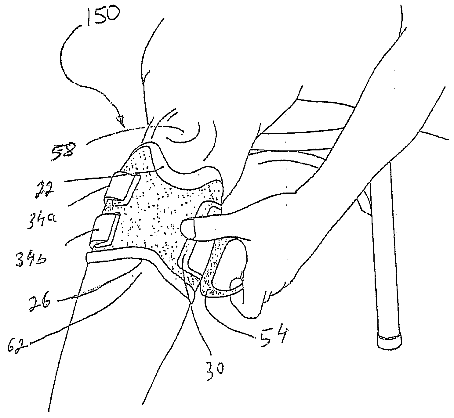
Consequently, objective biomechanical problems exist in donning the orthotic device and in locating the electrodes in exact position onto the limb.
Prior art neuroprosthetic devices differ in that they fail to enable facile, quick and accurate donning of the device by an impaired patient using a single hand, and particularly, when even that hand is shaky or otherwise unstable.
These devices can be inconvenient for the user.
Particularly cumbersome is the wiring, which is usually arranged to run along the leg under the clothing to connect the device components.
Consequently, use of the known devices, which are configured and dedicated to the anatomy and needs of a particular individual, is limited to that individual only, and further requires considerable expertise to reconfigure the device for transfer to another patient.
Neuroprosthetic devices require a significant and time-consuming set-up procedure carried out by a trained medical professional to fit the device to the anatomy of the limb, position the electrodes accurately over the motor point, and adjust the stimulation parameters when transferring the device to another patient.
Parts of the orthosis are in prolonged contact with the skin during a session of use, and existing devices have no provision for hygienically passing the orthosis from the leg of one patient on to another.
However, activation of the leg muscles by electrical stimulation requires typically high stimulation currents.
The level of muscle activation is often limited in the typical patient by his individual tolerance to activation of these skin pain sensors.
This electrode geometry and arrangement for increasing muscle force output and reducing sensory discomfort is too large to fit within the prior art narrow band design of the orthosis.
The wide orthosis design introduces new problems concerned with fitting and self-placement.
Moreover, the larger dimensions of the orthosis appreciably compromise the ability of the orthosis to fit the contour of the limb segment, especially during limb extensions, flexions and gait.
However, the use of such an RF system necessitates integrating an RF transmitting unit, or head, within the foot sensor device.
The transmitting unit can be bulky and sensitive to humidity and mechanical stress.
This approach is disadvantageous in that the patient, who is often hemi-plegic or may suffer from other disorders, is required to add the donning of an additional item—the sock—to his routine.
This unintuitive action is particularly problematic for patients who need or prefer to don the FES orthotic device in an unassisted fashion.
A further disadvantage of this design is that the semi-rigid spine may rub against the foot and heel.
These forces may impede the efficacy and sensitivity of the foot sensor.
A further disadvantage lies in the limited ability to adjust the electronic head of the pressure switch to different shoe heights: the electronic head protrudes excessively from low-rimmed shoes, and cannot be fitted to shoes or boots in which the rim is at or above the height of the electronic head.

Method used


Image

  • Gait modulation system and method
  • Gait modulation system and method
  • Gait modulation system and method

Examples


Embodiment Construction

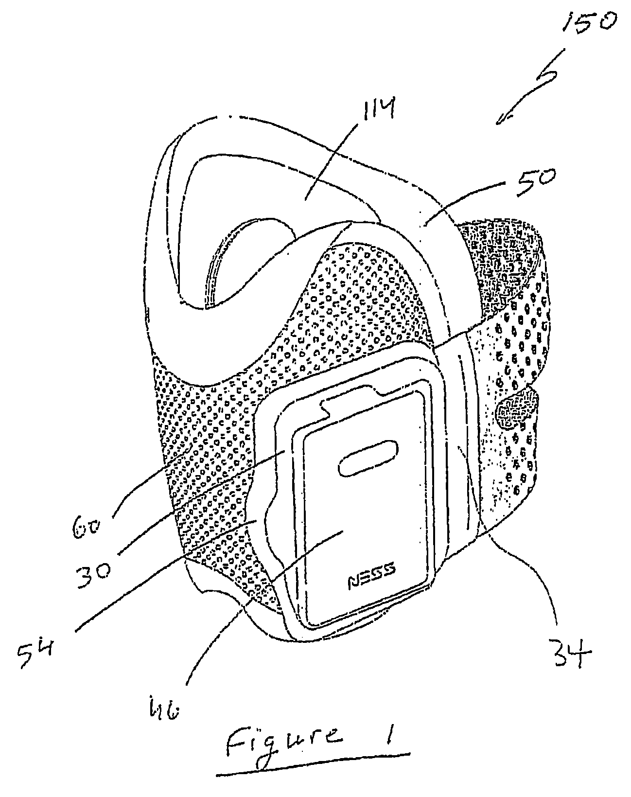
[0165]One aspect of the present invention is an improved electrical stimulation orthosis and method, and more particularly, a functional electrical stimulation (FES) orthosis for users suffering from gait problems such as drop foot. The orthosis can easily be donned on the leg, even by patients suffering from an impaired hand.

[0166]Before explaining at least one embodiment of the invention in detail, it is to be understood that the invention is not limited in its application to the details of construction and the arrangement of the components set forth in the following description or illustrated in the drawing. The invention is capable of other embodiments or of being practiced or carried out in various ways. Also, it is to be understood that the phraseology and terminology employed herein is for the purpose of description and should not be regarded as limiting.

[0167]Referring now to the drawings, FIG. 1 is a perspective view of the inventive FES gait modulation orthosis 150; FIG. 2...


PUM


Abstract

An electrical stimulation orthosis and method therefor, the orthosis including: (a) an at least semi-rigid frame configured to substantially envelop a limb segment, the frame having at least one first complementary mechanical fastener associated therewith; (b) a surface electrical stimulation electrode assembly associated with, and supported by, the frame, the assembly having a surface stimulation electrode for contacting at least one stimulation point on the limb segment, the surface electrode assembly having an electrode base for electrically associating, via the frame, with a stimulator unit for providing a stimulation signal to the surface electrode, the electrode base having a top face for receiving the stimulation electrode, and a bottom face having at least one second complementary mechanical fastener, the first and second fasteners adapted for reversible attachment and detachment, at a plurality of locations on the frame, thereby enabling the electrical stimulation electrode assembly to be adjustably and reversibly positioned on the frame.

Description

FIELD AND BACKGROUND OF THE INVENTION[0001]The present invention relates to gait modulation systems and methods therefor, and more particularly, to a functional electrical stimulation (FES) orthosis device and a sensor device for such gait modulation systems, and to method of using such devices.[0002]It is known that pathologies of the neuromuscular system due to disease or trauma to the central nervous system, such as stroke, spinal cord injury, head injury, cerebral palsy and multiple sclerosis, can impede proper limb functioning of the hands or legs. Gait, the biomechanical description of walking, can suffer static and dynamic parameter variations due to neuromuscular impairments, which cause non-symmetrical walking, reduced walking speed and reduced walking stability.[0003]Drop foot describes the gait attributable to weak or uncoordinated activation of the ankle dorsi-flexors due to disease or trauma to the central nervous system. Patients suffering from drop foot tend to drag t...

Claims


Application Information

Patent Timeline
IPC IPC(8): A61F5/00A61N1/00
CPCA61B5/1038A61B5/6807A61N1/36003A61F5/01A61B5/6828
Inventor DAR, AMITSHALEV, YOSSEFBAR-OR, JONATHANNATHAN, ROGER
Owner BIONESS NEUROMODULATION
Learn More