Fuel injection control apparatus

a technology of control apparatus and fuel injection, which is applied in the direction of electrical control, process and machine control, instruments, etc., can solve the problems of increasing the frequency of resumption of fuel injection, and not being able to meet so as to achieve the effect of reducing the minimum quantity of fuel injection

Active Publication Date: 2009-07-09
HITACHI ASTEMO LTD
View PDF19 Cites 24 Cited by
  • Summary
  • Abstract
  • Description
  • Claims
  • Application Information

AI Technical Summary

Benefits of technology

[0016]According to the present invention, the minimum quantity of fuel injection can be reduced without reducing the maximum quantity of fuel injection.

Problems solved by technology

Likewise, the chances of fuel cuts for not injecting the fuel when motive power output of the internal combustion engine is unnecessary are increasing for reduction in fuel consumption rate, and this tendency is, in turn, increasing the frequency of resumption of fuel injection.
There has been the problem, however, that the methods described in Japanese Patent No. 4768723 and 3562125 do not suffice to meet the minimum fuel injection quantity required.

Method used


Image

  • Fuel injection control apparatus
  • Fuel injection control apparatus
  • Fuel injection control apparatus

Examples


first embodiment

[0026]A configuration and operation of a fuel injection control apparatus according to the present invention will be described hereunder using FIGS. 1 to 8.

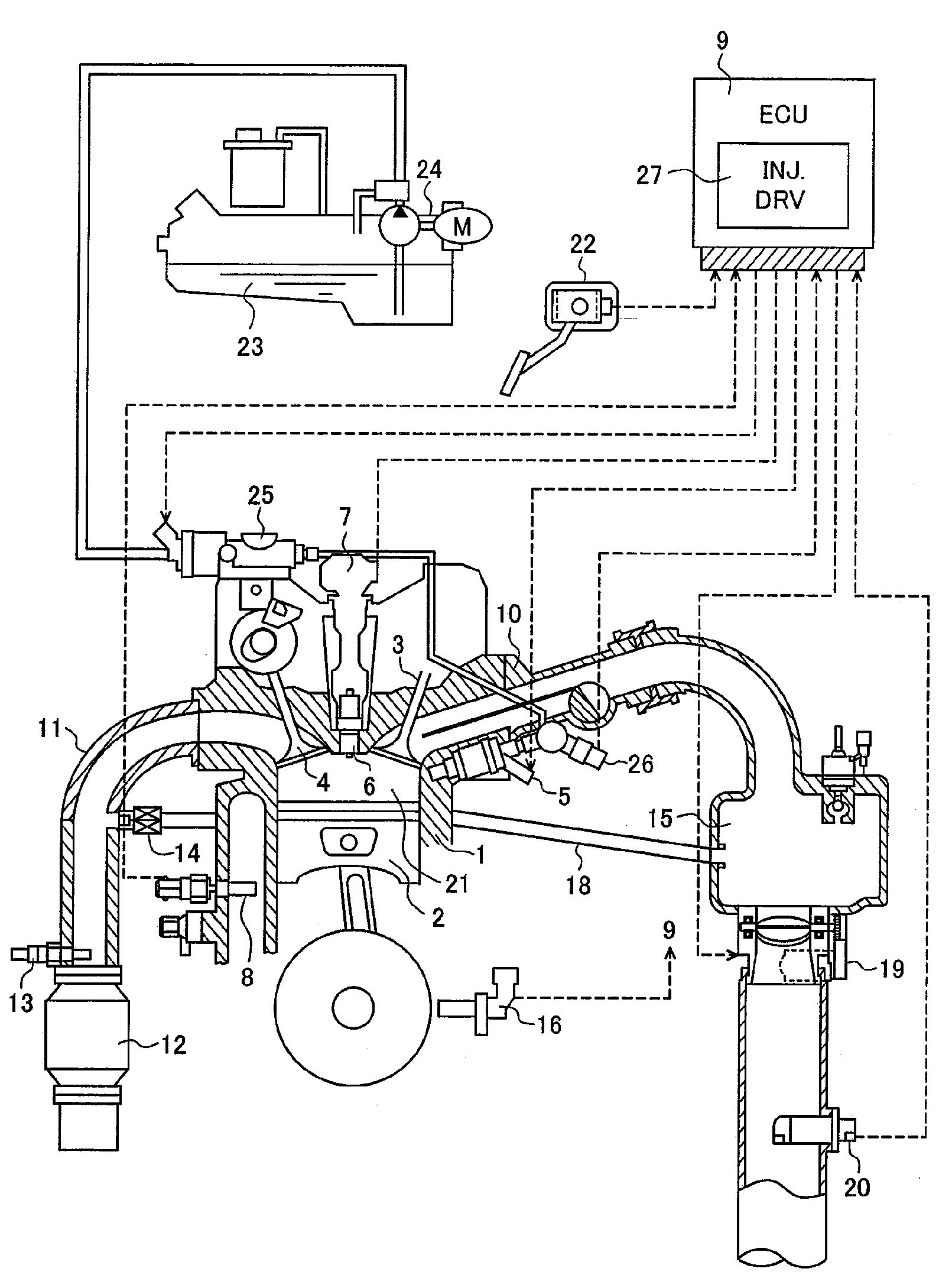
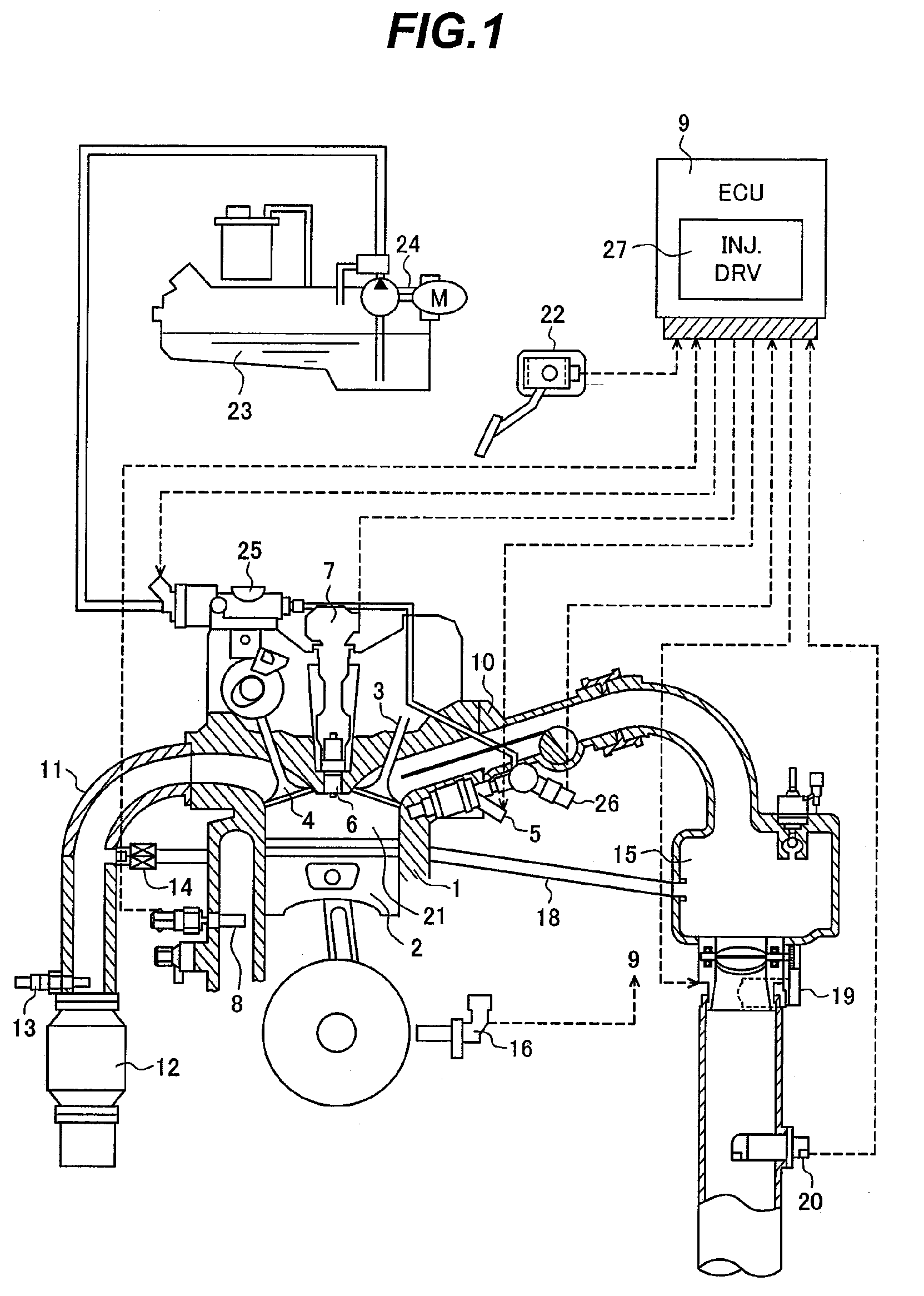
[0027]First, a configuration of an internal combustion engine system with the fuel injection control apparatus of the present embodiment will be described using FIG. 1. FIG. 1 is a block diagram of the internal combustion engine system with the fuel injection control apparatus according to the first embodiment of the present invention.

[0028]The engine 1 includes a piston 2, an air suction valve 3, and an exhaust valve 4. Suction air flows into a throttle valve 19 through an air flowmeter (AFM) 20, and is supplied from a collector 15 that is a branch section, through an air suction pipe 10 and the suction valve 3, to a combustion chamber 21 of the engine 1. Fuel is supplied from a fuel tank 23 to the internal combustion engine by a low-pressure fuel pump 24, and the supplied fuel is boosted up to a pressure required for fuel injec...

second embodiment

[0040]FIG. 3 is a timing chart showing the excitation current flowing into the injector 53 under the control of the fuel injection control apparatus in the present invention.

[0041]In FIG. 3, the horizontal axes denote time “t”. The vertical axis in section (A) of FIG. 3 denotes the excitation current Iex flowing into the fuel injector 53. The vertical axis in section (B) of FIG. 3 denotes the driving pulse Ti supplied from the microcomputer 57 to the driving IC 56. The vertical axis in section (C) of FIG. 3 denotes the on / off states of the switching element 50. The vertical axis in section (D) of FIG. 3 denotes the on / off states of the switching element 51. The vertical axis in section (E) of FIG. 3 denotes the on / off states of the switching element 52.

[0042]At time t0, before the driving pulse Ti shown in section (B) of FIG. 3 changes to a High (high) state, when a precharge current Ipre is to be supplied to the fuel injector 53 for a fixed time as shown in section (A) of FIG. 3, t...

third embodiment

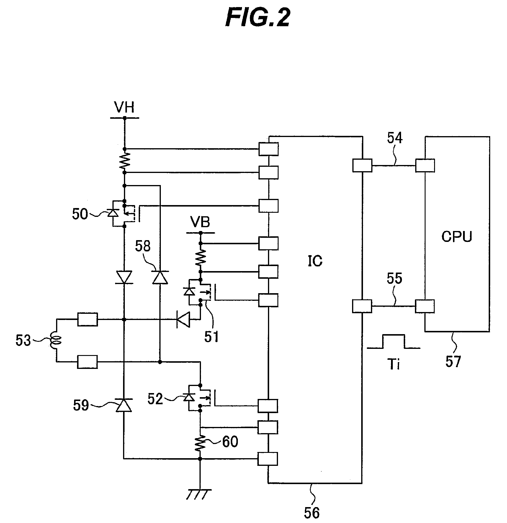
[0099]A configuration and operation of a fuel injection control apparatus according to the present invention will be described hereunder using FIG. 9. A configuration of an internal combustion engine system with the fuel injection control apparatus of the present embodiment is substantially the same as in FIG. 1. Also, the configuration of the fuel injection control apparatus according to the present embodiment is substantially the same as in FIG. 2.

[0100]FIG. 9 is a timing chart showing the excitation current flowing into the injector under the control of the fuel injection control apparatus in the third embodiment of the present invention.

[0101]The present embodiment, unlike those shown in FIGS. 3 and 8, can dispense with mode switching in steps S30-S50 of FIG. 7.

[0102]At time t0, before the driving pulse Ti shown in section (B) of FIG. 9 changes to a High (high) state, when the precharge current Ipre is to be supplied to the fuel injector 53 for a fixed time as shown in section (...


PUM


Abstract

To provide a fuel injection control apparatus capable of reducing the minimum quantity of fuel injection without reducing the maximum quantity of injection.
For fuel injector valve opening, a driving circuit 56 supplies an electric current from a high-voltage power supply VH to the fuel injector 53, then after valve opening, switches the high-voltage power supply VH to a low-voltage power supply LV, and retains the open state of the valve. A microcomputer 57 is adapted such that for opening the valve of the fuel injector, the microcomputer, after supplying the current from the high-voltage power supply to the injector 53, discharges the current rapidly for a decrease below a first current level Ihold1 at which the open state of the valve cannot be retained, and then controls the supply current to the injector 53 so as to supply a current of a second current level Ihold2 at which the open state of the valve can be retained.

Description

BACKGROUND OF THE INVENTION[0001]1. Field of the Invention[0002]The present invention relates generally to fuel injection control apparatuses of internal combustion engines, and more particularly, to a fuel injection control apparatus capable of improving its minimum fuel injection quantity.[0003]2. Description of the Related Art[0004]Internal combustion engines have a fuel injection control apparatus that computes the appropriate quantity of fuel according to a particular operational state and drives a fuel injector used to supply the fuel. The fuel injector opens or closes its valve, part of the injector, by utilizing the magnetic force generated by the flow of current through a solenoid, and thus injects the fuel or stops the injection. The quantity of fuel injected is determined primarily by the differential between the pressure of the fuel and the atmospheric pressure of the injector nozzle and the time during which the valve is maintained in the open state and the fuel is inje...

Claims


Application Information

Patent Timeline
Patent Type & Authority Applications(United States)
IPC IPC(8): F02D41/30F02M51/00
CPCF02D41/20F02D2041/2058F02D2041/2044
Inventor MIYAKE, TAKAOTOYOHARA, MASAHIROMAYUZUMI, TAKUYAISHIKAWA, TOHRUOURA, RYOICHI
Owner HITACHI ASTEMO LTD
Why Eureka
Try Eureka