Anisotropic electrically conductive film and connection structure

a technology of electrically conductive film and connection structure, which is applied in the direction of conductive materials, non-conductive materials with dispersed conductive materials, synthetic resin layered products, etc., can solve the problems of low connection reliability, low adhesion strength of connections, and connection itself, and achieve high adhesion strength

Active Publication Date: 2009-07-16
DEXERIALS CORP
View PDF1 Cites 34 Cited by
  • Summary
  • Abstract
  • Description
  • Claims
  • Application Information

AI Technical Summary

Benefits of technology

[0012]It is desirable to the present invention to provide an anisotropic electrically conductive film that may exhibit a high adhesion strength in the stress relieved state, and a connection structure employing the same.

Problems solved by technology

Meanwhile, if an anisotropic electrically conductive film formed of an acrylic resin composition is compared to an anisotropic electrically conductive film formed of an epoxy resin composition, the former has deficiencies that are connected with low adhesion strength, such as a defect in the connection itself and in low conduction reliability subsequent to connection.
It is not possible with the known film to satisfy the requirements which are contradictory to each other, that is, the requirement for achieving the elevated adhesion strength and the requirement for realization of a stress relieved state, at the same time.
However, the anisotropic electrically conductive film disclosed in Patent Publication 1 is not of a sufficiently high molecular weight.
Specifically, there is a statement in Patent Publication 1 that a polymer material with a weight averaged molecular weight not less than 1000000 is inferior in its dissolution performance and is difficult to mix in the composition.
That is, with the thermosetting acrylic resin composition in the past, it is difficult to elevate the adhesion strength in a stress-relieved state.

Method used


Image

  • Anisotropic electrically conductive film and connection structure
  • Anisotropic electrically conductive film and connection structure

Examples


example

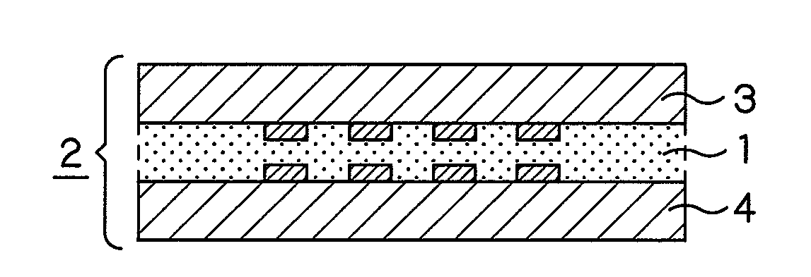
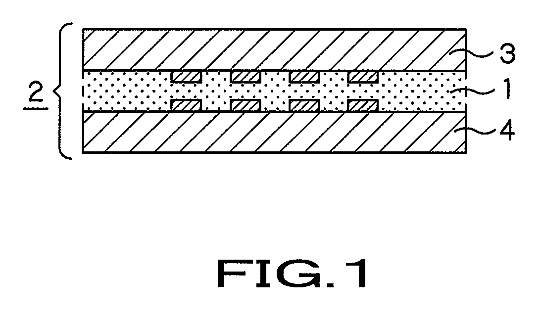
[0042]An anisotropic electrically conductive film of the present invention will now be described with reference to an Example of the present invention. This Example will be explained in comparison with Comparative Examples 1 to 5 as tabulated in Table 1.

[0043]In the Example, methylethylketone (MEK) is used as a solvent. To 100 parts by weight of MEK, a phenoxy resin, a liquid acrylic ester, a peroxide based initiator, the acrylic rubber containing the hydroxyl groups, a phosphorus-containing acrylic ester, polybutadiene based fine particles, a silane coupling agent and electrically conductive particles were added in proportions (parts by weight) shown in Table 1. The resulting mass was mixed together by a mixer, and the so formed mixture was coated by a bar coater on a polyethylene terephthalate film, 50 μm in thickness, already processed with peeling. The resulting coated product was dried at 80° C. for five minutes to produce an anisotropic electrically conductive film 20 μm in th...


PUM

PropertyMeasurementUnit
temperatureaaaaaaaaaa
adhesion strengthaaaaaaaaaa
particle sizeaaaaaaaaaa

Abstract

An anisotropic electrically conductive film formed by a thermosetting acrylic resin composition is disclosed. The composition contains at least a thermosetting agent (A), a thermo-settable ingredient (B), an acrylic rubber containing hydroxyl groups (C), organic fine particles (D) and electrically conductive particles (E). The thermo-settable ingredient (B) may include a phosphorus-containing acrylic ester (b1). The weight averaged molecular weight of the acrylic rubber containing the hydroxyl groups (C) is not less than 1000000. The organic fine particles (D) include polybutadiene-based fine particles (d1).

Description

BACKGROUND OF THE INVENTION[0001]1. Field of the Invention[0002]This invention relates to an anisotropic electrically conductive film obtained on dispersing electrically conductive particles in a thermosetting acrylic resin composition and which exhibits a high adhesion strength, and to a connection structure that makes use of the same.[0003]The present application claims priority rights based on the Japanese Patent Application 2007-115929, filed in Japan on Apr. 25, 2007. This patent application of the senior filing date is to be incorporated herein by reference.[0004]2. Description of Related Art[0005]In the field of the packaging technology, an anisotropic electrically conductive film has now come into widespread use because the film allows for a simpler connection process and also is lead-free. As this anisotropic electrically conductive film, such a film composed of a thermosetting epoxy resin composition was so far used in view of connection reliability and resistance against ...

Claims


Application Information

Patent Timeline
Patent Type & Authority Applications(United States)
IPC IPC(8): H05K1/16H01B1/12
CPCC08G2650/56C08L33/066C08L71/00H01B1/20H01R4/04Y10T428/254H05K2201/0133H05K2201/0212H05K3/323C08L2666/04Y10T428/31855H01R11/01H01B1/12H05K1/16C09J133/14
Inventor AKUTSU, YASUSHISATO, DAISUKEHAYASHI, SHINICHI
Owner DEXERIALS CORP
Why Eureka
Try Eureka