Method of Making a Combustion Turbine Component from Metallic Combustion Turbine Subcomponent Greenbodies

a technology of combustion turbine and green body, which is applied in the field of metalurgical field, can solve the problems of limited size of combustion turbine components that may be formed by casting, limitation of the size of surface features of combustion turbine components that may be formed, and difficulty in forging process formation of small surface features of combustion turbine components. , to achieve the effect of increasing the surface area of combustion turbine components, enhancing heat dissipation properties, and high temperature resistan

Inactive Publication Date: 2009-07-23
MIKRO SYSYTEMS INC +1
View PDF28 Cites 96 Cited by
  • Summary
  • Abstract
  • Description
  • Claims
  • Application Information

AI Technical Summary

Benefits of technology

[0022]At least one of the plurality of metallic combustion turbine subcomponent greenbodies may be formed to have a plurality of surface features, each with a dimension less than 200 μm. These surface features may provide the combustion turbine component

Problems solved by technology

There may, however, be limitations on the size of the combustion turbine components that may be formed by casting.
Likewise, there may be limitations on the size of surface features of the combustion turbine components that may be formed (e.g. it may not be possible to form surface features having dimensions below a certain size).
However, due to the fine grain structure, a forged combustion turbine component generally exhibits relatively low resistance to creep and may thus be unsuitable for use in certain applications Subsequent heat treatment can promote grain growth, however, and it is may be easier to control grain size in a forging than a casting.
In addition, the formation of small surface features on such a combustion turbine component during the forging process may be difficult.
Since forgings are generally solid shapes and cooling passages are later machined into the forging, it may be difficult to machine fine scale internal feature

Method used


Image

  • Method of Making a Combustion Turbine Component from Metallic Combustion Turbine Subcomponent Greenbodies
  • Method of Making a Combustion Turbine Component from Metallic Combustion Turbine Subcomponent Greenbodies
  • Method of Making a Combustion Turbine Component from Metallic Combustion Turbine Subcomponent Greenbodies

Examples


Embodiment Construction

[0035]The present invention will now be described more fully hereinafter with reference to the accompanying drawings, in which preferred embodiments of the invention are shown. This invention may, however, be embodied in many different forms and should not be construed as limited to the embodiments set forth herein. Rather, these embodiments are provided so that this disclosure will be thorough and complete, and will fully convey the scope of the invention to those skilled in the art. Like numbers refer to like elements throughout.

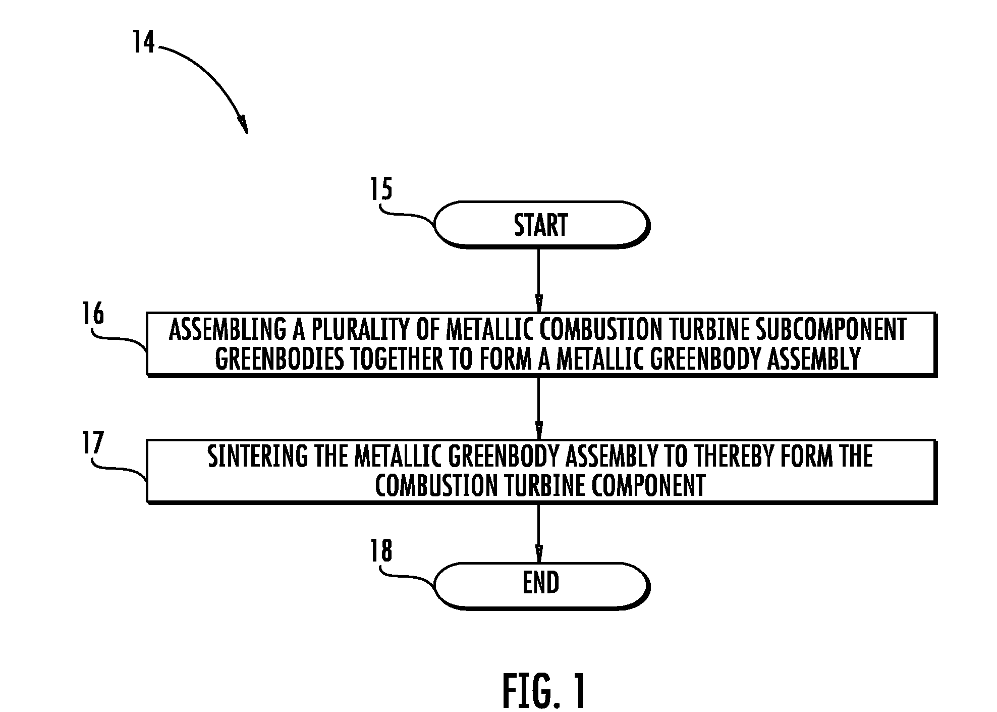
[0036]Referring initially to the flowchart 14 of FIG. 1, a first embodiment of a method of making a combustion turbine component is now described. After the start (Block 15), at Block 16 a plurality of metallic combustion turbine subcomponent greenbodies are assembled together to form a metallic greenbody assembly. The metallic greenbody assembly has a shape closely resembling that of the final combustion turbine component, but has a greater porosity, a le...


PUM

PropertyMeasurementUnit
Lengthaaaaaaaaaa

Abstract

A method of making a combustion turbine component includes assembling a plurality of metallic combustion turbine subcomponent greenbodies together to form a metallic greenbody assembly and sintering the metallic greenbody assembly to thereby form the combustion turbine component. Each of the plurality of metallic combustion turbine subcomponent greenbodies may be formed by direct metal fabrication (DMF). In addition, each of plurality of metallic combustion turbine subcomponent greenbodies may include an activatable binder and the activatable binder may be activated prior to sintering.

Description

CROSS REFERENCE TO RELATED APPLICATIONS[0001]This application claims the benefit of the filing date of U.S. Provisional Patent, Ser. No. 61 / 022,952, filed on Jan. 23, 2008.GOVERNMENT CONTRACT[0002]The U.S. Government has a paid-up license in this invention and the right in limited circumstances to require the patent owner to license others on reasonable terms as provided for by the terms of contract No. DE-FC26-05NT42644 awarded by the Department of Energy.FIELD OF THE INVENTION[0003]The present invention relates to the field of metallurgy, and, more particularly, to methods of making a combustion turbine component from a plurality of metallic combustion turbine subcomponent greenbodies.BACKGROUND OF THE INVENTION[0004]A combustion turbine typically includes, in a serial flow relationship, a compressor section to compress the entering airflow, a combustion section in which a mixture of fuel and the compressed air is burned to generate a propulsive gas flow, and a turbine section tha...

Claims


Application Information

Patent Timeline
IPC IPC(8): B22D17/00
CPCB22F5/009B22F2998/00B22F2998/10F05B2230/22B22F7/062Y10T156/10B22F3/1055B22F3/008B22F3/225B22F3/10B22F2005/005Y02P10/25B22F10/18B22F10/28B22F10/12
Inventor MORRISON, JAY A.LANE, JAY E.JAMES, ALLISTER W.
Owner MIKRO SYSYTEMS INC
Why Eureka
Try Eureka