
Method for controlling enthalpy in air conditioning systems

a technology of air conditioning system and enthalpy, which is applied in the direction of static/dynamic balance measurement, heating type, instruments, etc., can solve the problems of ballard not addressing enthalpy or humidity control, and achieve the effect of reducing aspergillus repens and reducing some of the causes

Inactive Publication Date: 2009-07-30
TONNER ROBERT BRIAN
View PDF0 Cites 25 Cited by
  • Summary
  • Abstract
  • Description
  • Claims
  • Application Information

AI Technical Summary

Benefits of technology

[0018]Accordingly it is therefore an object of the present invention to strictly control the maximum humidity in a space without the use of humidity sensors in the airflow ducts or in the space to cooled, especially in high humidity warm climates in order to dramatically reduce Aspergillus Repens and thus to control the growth of dust mite populations and ultimately reduce some of the causes of asthma and other related conditions.
[0019]It is a further object of the present invention to strictly limit relative humidity so that the human response will be to raise the set point of the cooling thermostat in order to reduce heat gains and thereby reduce energy costs associated with cooling.
[0022]It is yet another object of this invention to provide a means to adjust the operation of the air conditioning compressors that have a variable output capacity to closely match the needs of the system in order to reduce energy consumption and maximize occupant comfort.

Problems solved by technology

Ballard does not address enthalpy, or humidity control.

Method used


Image

  • Method for controlling enthalpy in air conditioning systems
  • Method for controlling enthalpy in air conditioning systems
  • Method for controlling enthalpy in air conditioning systems

Examples


Embodiment Construction

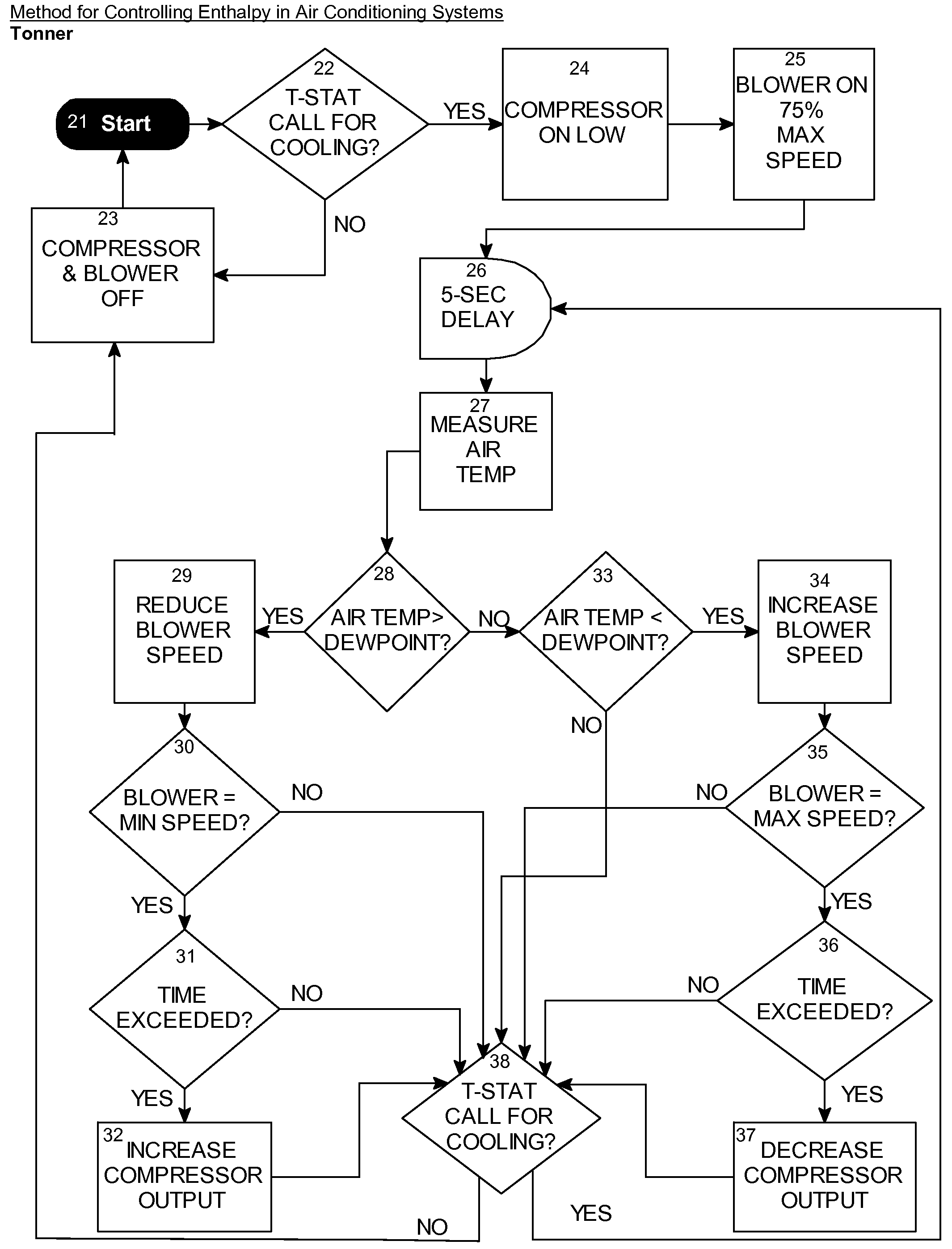
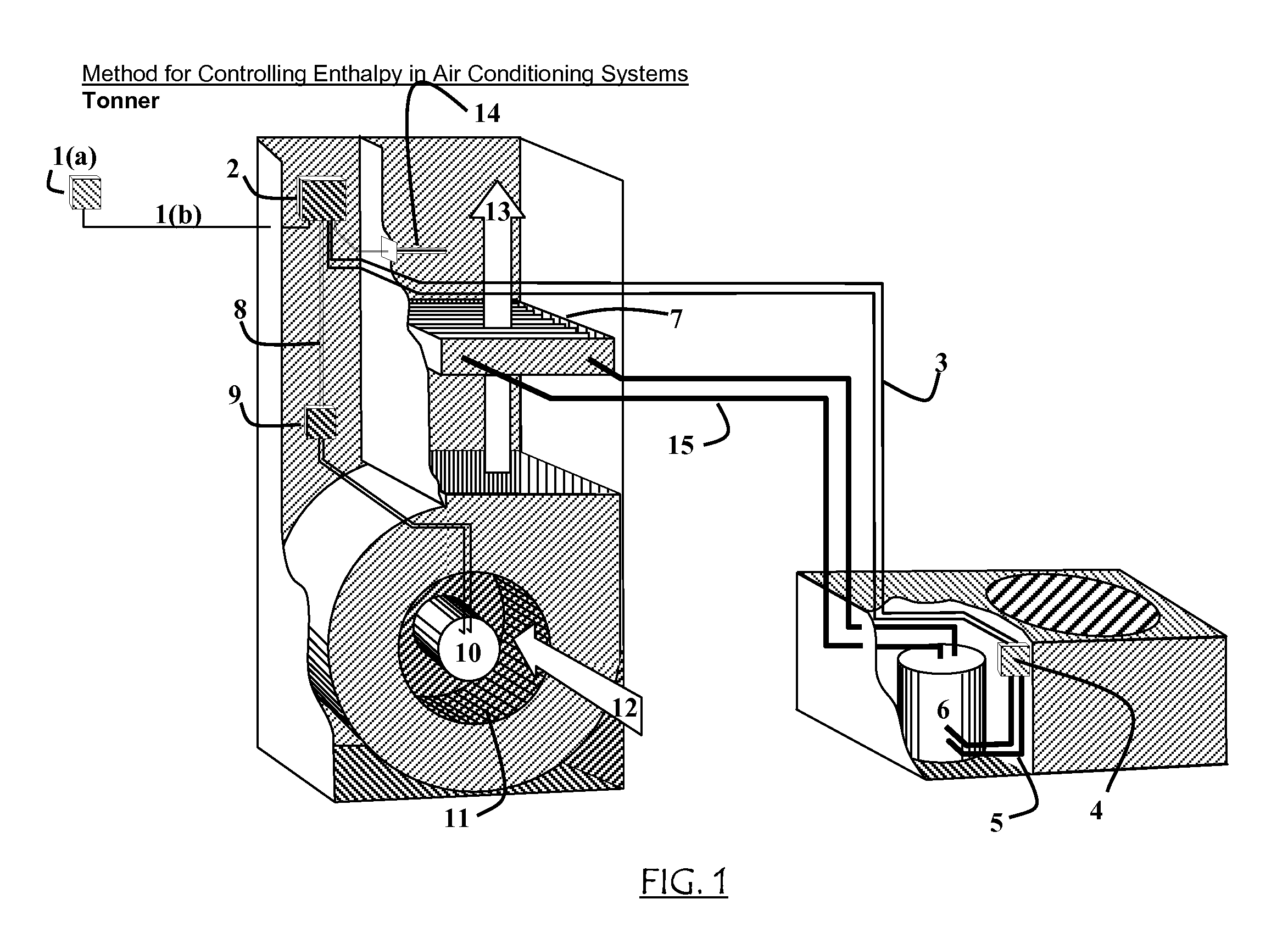
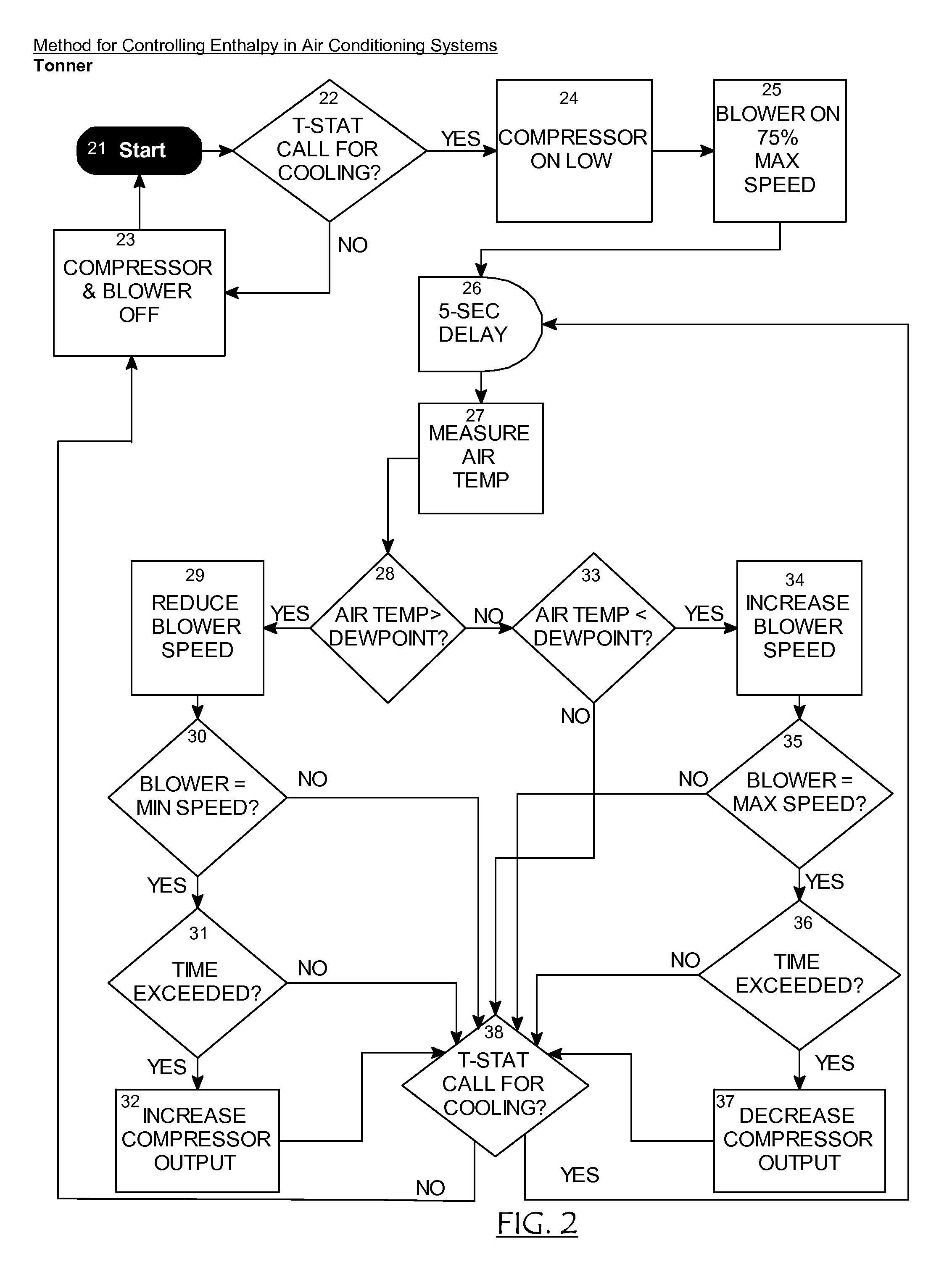
[0030]Now, with reference to FIG. 1 there is disclosed an air conditioning system which is well known to those skilled in the arts. Signal and control wiring is simplified for the purposes of this drawing in order to disclose the relationships of the devices and the method. Wiring means to provide electrical power are well known to those skilled in the arts and are not an object of this invention. Signal wires are also simplified and shown in greater detail in FIG. 3. The room thermostat 1(a) monitors room sensible air temperature and the desired room temperature set point as defined by the occupant. Upon detecting air temperature above the set point the thermostat 1(a) closes an internal switch, providing a control signal via thermostat wires 1(b) to enthalpy control unit 2. Enthalpy control unit 2, which is microprocessor based controller known to those skilled in the art, provides a control signal via the compressor control wires to the compressor actuating means 4. Compressor ac...


PUM


Abstract

In an air conditioning system a method for controlling enthalpy in the environment of a structure is disclosed. The blower speed is controlled in such a manner as to maintain the prescribed dew point temperature of the air passing over the evaporator coils. When the air to be cooled contains high relative humidity, a greater quantity of latent heat is rejected into the evaporator, resulting in less sensible heat being rejected. This results in higher sensible temperature of air passing over the evaporator coils and thus the blower speed is reduced in and effort to maintain dew point. Maintaining the prescribed dew point ensures that the air in the space is continuously maintained at the optimum humidity levels without the use of humidity sensors. Enthalpy is determined by observing relative blower speed and the refrigeration compressor is modulated based on the blower speed.

Description

BACKGROUND OF THE INVENTION[0001]The present invention relates to the cooling and dehumidification of buildings using air conditioning. The US Environmental Protection Agency cites the ASHRAE Standard 55-1992 Thermal Environmental Conditions for Human Occupancy, which recommends keeping relative humidity between 30% and 60%, with below 50% preferred to control dust mites[0002]Dust mites generally live on shed human skin cells, which are pre-digested by the fungus Aspergillus repens. This fungus thrives above 70% RH. An average person sheds about 1.5 grams of skin a day (approximately 0.3-0.45 kg per year), which is enough to feed roughly a million dust mites. The house dust mite is one of the most significant sources of allergens, implicated in allergic asthma, rhinitis, conjunctivitis and dermatitis. One of the more important proteins responsible for the allergic reaction is DerP1, a protease digestive enzyme found in dust mite feces.[0003]Typical air conditioning systems merely co...

Claims


Application Information

Patent Timeline
Patent Type & Authority Applications(United States)
IPC IPC(8): G05D23/00F25B41/00
CPCF24F11/001F24F11/0079Y02B30/746G05D23/1927F24F2013/221G05D22/02G05D23/19G05D27/02F24F11/30F24F2110/00F24F11/77Y02B30/70F24F11/76F24F11/63
Inventor TONNER, ROBERT BRIAN
Owner TONNER ROBERT BRIAN
Learn More