Applicator and apparatus for heating samples by microwave radiation

a microwave radiation and microwave technology, applied in microwave heating, chemical vapor deposition coatings, coatings, etc., can solve the problems of inhomogeneous heating of samples, small penetration depth of microwaves into samples, and gas generation or expansion inside the vessel will necessarily increase the internal pressure, so as to achieve effective microwave radiation transmission, increase the dielectric constant, and suitable impedance matching

Inactive Publication Date: 2009-08-06
ANTON PAAR
View PDF21 Cites 19 Cited by
  • Summary
  • Abstract
  • Description
  • Claims
  • Application Information

AI Technical Summary

Benefits of technology

[0024]Due to the fact that part of the microwave radiation propagating within the transmission duct will be absorbed by the sample arranged at or close to the interface, the amplitude of the microwaves would normally decrease along the direction of propagation. According to the invention, this decrease is compensated by employing a tapering transmission duct where the tapering portion enables the maintenance of an enhanced field strength along the interface despite the fact that part of the microwave energy is leaving the transmission duct via the interface in order to heat the sample. Essentially, the tapering microwave applicator of the present invention enables the maintenance of a high energy density of the microwave radiation along the microwave-permeable interface and thus achieving high absorption rates within the neighbouring sample volume.
[0035]The cavity of the microwave applicator preferably has an essentially cylindrical shape with a longitudinal axis defined by the centre axis of the cylinder. The tapering portion of the transmission duct is adapted to form a jacket surrounding the cavity with the interface forming an inner wall of the jacket. The jacket has a longitudinal axis which is preferably arranged parallel to the longitudinal axis of the cavity. Accordingly, the cavity of microwave applicator according to the invention exhibits superior resistance to pressure allowing a heating of the sample under increased pressure.

Problems solved by technology

Further, when, for example, digestion methods for analytical purposes are used, the generation or expansion of gases inside the vessel will necessarily increase the internal pressure.
However, when larger amounts of samples are heated with microwave radiation, the problem arises that the depth of penetration of microwaves into the sample is relatively small.
Specifically, insufficient heat transfer will often lead to inhomogeneous heating of the sample.
Stirring of the sample only partly mitigates this problem because the larger the sample volume, the more difficult it is to reliably control the stirring and heating process.
In addition, during the course of the chemical or physical process induced by microwave radiation, drastic variations of the dielectric properties of the samples, solvents or reactants may occur.
In summary, in these prior art methods it is rather difficult to ensure that an effective, uniform and reproducible heating of samples, in particular larger amounts of samples, is achieved.
While able to heat food, this appliance hardly produces enough radio frequency energy to heat larger samples to the temperatures required in microwave-assisted chemistry.
Due to the decreasing field strength in the direction of propagation of microwave radiation, the heating of the sample will not be homogeneous either.
This device is not suitable for heating liquid samples.
While the apparatus of U.S. Pat. No. 4,067,687 might be sufficient to control the fluency of hydrocarbon fluids, no homogenous heating of the sample is possible.
This device does not allow homogenous heating of the fluid within the pipe either.
The provision of ridges renders the internal structure of the waveguide rather complex.

Method used


Image

  • Applicator and apparatus for heating samples by microwave radiation
  • Applicator and apparatus for heating samples by microwave radiation
  • Applicator and apparatus for heating samples by microwave radiation

Examples


Embodiment Construction

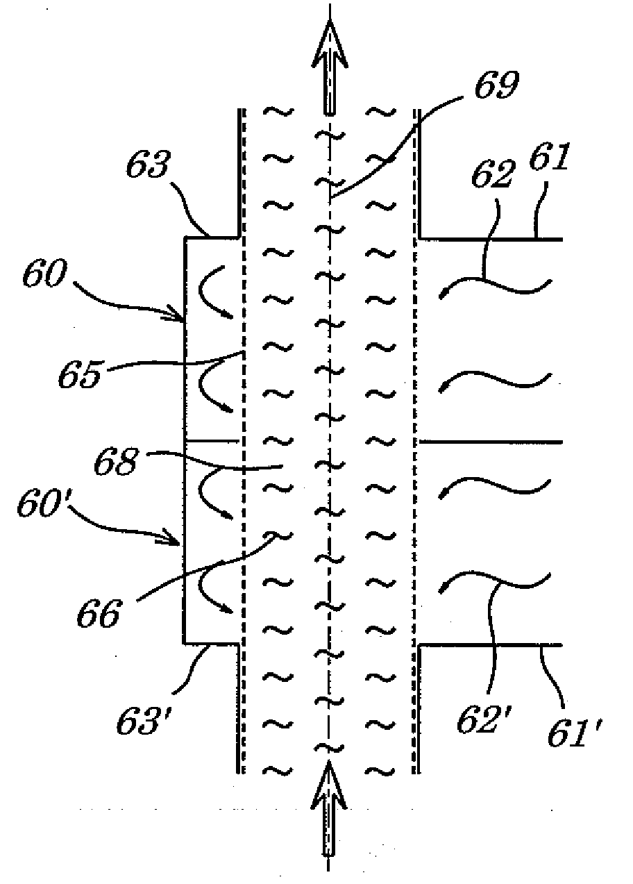
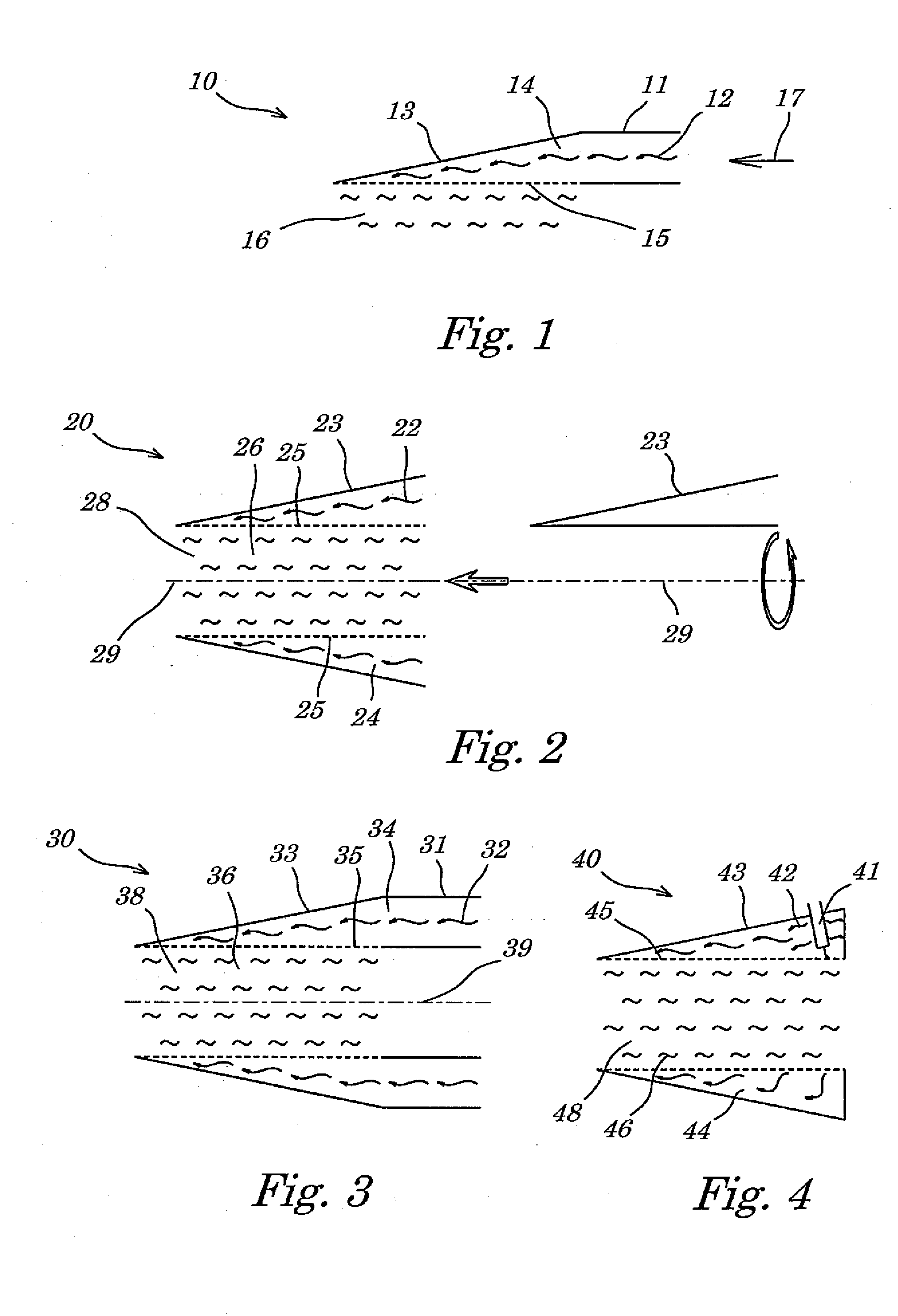
[0060]In FIG. 1 a first embodiment of the microwave applicator 10 according to the invention is shown. The applicator 10 consists of a waveguide 11 coupling microwave radiation (depicted as undulating arrows 12) which is transferred from a source of microwave radiation (not shown in FIG. 1) to a tapering portion 13 of the applicator 10. Waveguide 11 and tapering portion 13 of the applicator are made from conductive metal sheets and define the external walls of a hollow tube 14 in which the microwave radiation 12 propagates. In a portion of the wall defining the tapering portion of the transmission duct 13, an interface 15 (depicted in dashed lines) is provided. The interface 15 made from a material which is partially permeable to microwave radiation. Beneath the interface 15, a sample 16 to be heated by microwave radiation is arranged. Although the general direction of propagation of the microwave radiation inside the applicator 10 is essentially parallel to the interface 15 as depi...


PUM

PropertyMeasurementUnit
wavelengthsaaaaaaaaaa
frequenciesaaaaaaaaaa
pressureaaaaaaaaaa

Abstract

The present invention relates a microwave applicator for heating a sample by microwave radiation which is transmitted via an at least partially tapering transmission duct from a microwave source to a cavity adapted to receive the sample to be heated. The transmission duct has at least one external wall, said wall defining an internal space for the propagation of said microwave radiation and comprising an interface which is at least partially permeable to said microwave radiation. The interface is at least partially arranged within said tapering portion of the duct. The duct is adapted to form a jacket surrounding the cavity with said interface forming an inner wall of said jacket.

Description

RELATED APPLICATIONS[0001]This application claims the benefit of U.S. Provisional Application No. 61 / 025,921, filed Feb. 4, 2008, which is fully incorporated herein by reference.FIELD OF THE INVENTION[0002]The present invention concerns a microwave applicator for heating a sample by microwave radiation and a microwave-heating apparatus which comprises at least one of these applicators.BACKGROUND OF THE INVENTION[0003]In microwave-assisted chemistry, microwaves are used to initiate, drive, or otherwise enhance chemical or physical reactions. Generally, the term “microwaves” refers to electromagnetic radiation having a frequency within a range of about 108 Hz to 1012 Hz. These frequencies correspond to wavelengths between about 300 cm to 0.3 mm. Microwave-assisted chemistry is currently employed in a variety of chemical processes. Typical applications in the field of analytical chemistry include ashing, digestion and extraction methods. In the field of chemical synthesis, microwave ra...

Claims


Application Information

Patent Timeline
Patent Type & Authority Applications(United States)
IPC IPC(8): H05B6/70
CPCB01J19/126B01J2219/00063B01J2219/00094B01J2219/00141H05H1/46H05B6/806C23C16/00H01J7/24H05B6/70B01J2219/00162
Inventor KOTZIAN, HEIMOZACH, JOHANNESZENTNER, RAINER
Owner ANTON PAAR
Why Eureka
Try Eureka