Imaging system and method

a technology of imaging system and image, applied in the field of imaging system and method, can solve problems such as slow speed measurement, and achieve the effects of reducing edge effect errors, reducing speckle noise and edge effect errors, and reducing errors due to edge

Inactive Publication Date: 2009-08-06
NEPTEC
View PDF30 Cites 132 Cited by
  • Summary
  • Abstract
  • Description
  • Claims
  • Application Information

AI Technical Summary

Benefits of technology

[0104]Edge effects occur when a beam spot is split by a physical edge on two surfaces, or crosses a reflectance change at an interface between two surfaces on the same plane. When a laser spot is split between two surfaces at different ranges, the image of the spot on the detector array is the combined signal at two distances. Its peak center does not represent either ranges of these surfaces, as shown for example in FIG. 7. The center peak of a spot image can also be distorted when the returned beam is blocked by an edge, as shown in FIG. 9A, or the reflectance at an interface varies, as shown in FIG. 9B. There are many cases where edge effects can arise. Advantageously, the ability to focus the projected beam to a small beam size at the target surface provided by embodiments of the present apparatus enable errors due to edge effects to be significantly reduced.
[0105]An example of the improvements in reducing edge effect errors provided by an embodiment of the imaging apparatus over a conventional 3-D triangulation based imaging instrument can be appreciated with reference to FIGS. 10A and 10B. In this experiment, the edge of a micrometer head with a height of 3 mm was scanned. Each figure shows a graph of detected peak position as a function of distance (i.e. scan position). In FIG. 10A, a laser spot having a diameter of 50 μm and a lateral scanning step of 10 μm were used. As can be seen from the figure, edge induced range errors are on the order of 10 μm and the lateral edge can be determined on the 10 μm step as well.
[0106]In FIG. 10B, a laser spot of 1 mm and a lateral scan step of 50 μm were used. In this case, the location of the edge cannot be determined accurately. The range error on ...

Problems solved by technology

Although such instruments are capable of achieving higher resolutions than vision scanning probes, both the pan-ti...

Method used


Image

  • Imaging system and method
  • Imaging system and method
  • Imaging system and method

Examples


Embodiment Construction

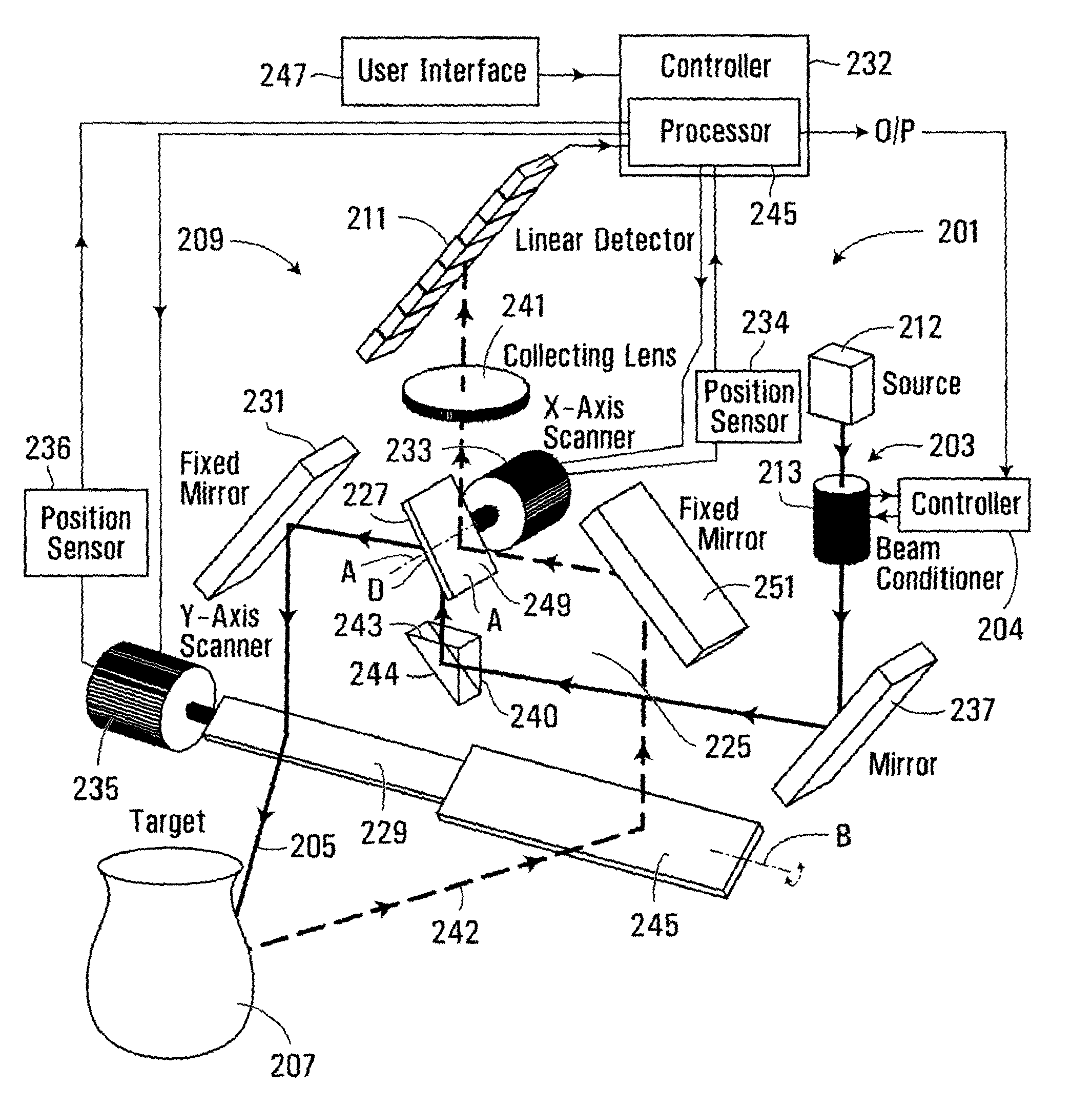
[0052]FIGS. 3, 4 and 5 show an example of an apparatus according to an embodiment of the present invention.

[0053]The apparatus generally shown at 201 comprises a projection system 203 for projecting a beam of energy 205 onto a target object 207, a receiving system 209 for receiving reflected beam energy from the target object 207 and a detector 211 for detecting the received beam energy.

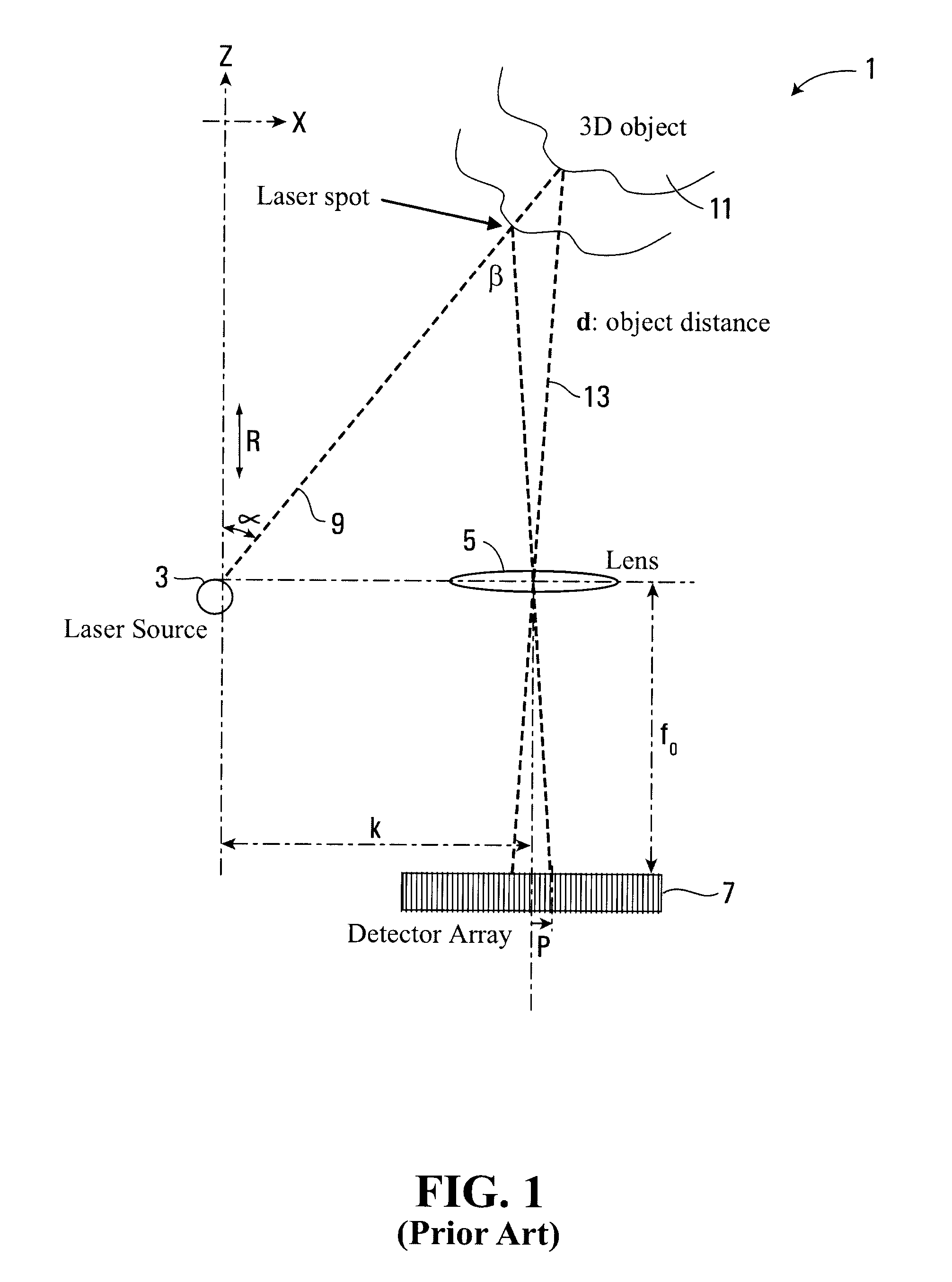
[0054]It will be appreciated that for a diffuse surface, the incident beam will be scattered in many different directions as for example shown by the ray lines 206 in FIG. 4, and a portion of the scattered radiation will be received by the receiving system and detected by the detector. The position of the received beam energy on the detector depends on the angle β between the projected beam and received reflected beam energy at the target surface. As the angle β depends on the range of the target surface, the position of the received beam energy at the detector provides a measure of the range.

[0055]I...


PUM


Abstract

An apparatus for measuring the coordinates of a point on the surface of an object comprises a projection system for projecting a beam of energy onto the surface of the object, a receiving system for receiving reflected beam energy from the target surface, and a detector for detecting the received energy. The projection system comprises a beam expander for expanding the width of the beam, and a focussing device for focussing the projected beam. The position of the reflected beam energy at the detector provides a measure of the range of the point on the target surface using triangulation and the direction of the projected beam provides the x and y coordinates. The focussing device can be controlled to vary the focal length of the projected beam and to control the beam size at the target object to vary the area of the target surface illuminated by the beam and thereby to control the resolution of the measurements.

Description

FIELD OF THE INVENTION[0001]The present invention relates to imaging systems and methods, and in particular, but not limited to, imaging systems capable of acquiring surface profile information.BACKGROUND OF THE INVENTION[0002]There are a number of existing systems which are used to measure the surface profile of an object in 3-dimensions. These 3-dimensional coordinate measurement machines (CCM) include vision scanning probes and contact probes. Some vision scanning probes use a system of rotating mirrors to perform a 2-dimensional raster scan across an object and use a triangulation method to measure the range. Other vision scanning probes use a pulsed laser and Time of Flight (TOF) technique to measure range information. High precision galvanometers may be used to drive the scanning mirrors and these enable high speed 2-dimensional scans to be performed. These instruments typically use a collimated laser beam having a diameter of approximately 1 mm (i.e. a diameter approaching th...

Claims


Application Information

Patent Timeline
IPC IPC(8): G01B11/24
CPCG01B11/24
Inventor ZHU, XIANGSMITH, I. CHRISTINEENGLISH, CHAD
Owner NEPTEC
Why Eureka
Try Eureka