

Magnetic toner
- Summary
- Abstract
- Description
- Claims
- Application Information
AI Technical Summary
Benefits of technology
Problems solved by technology
Method used
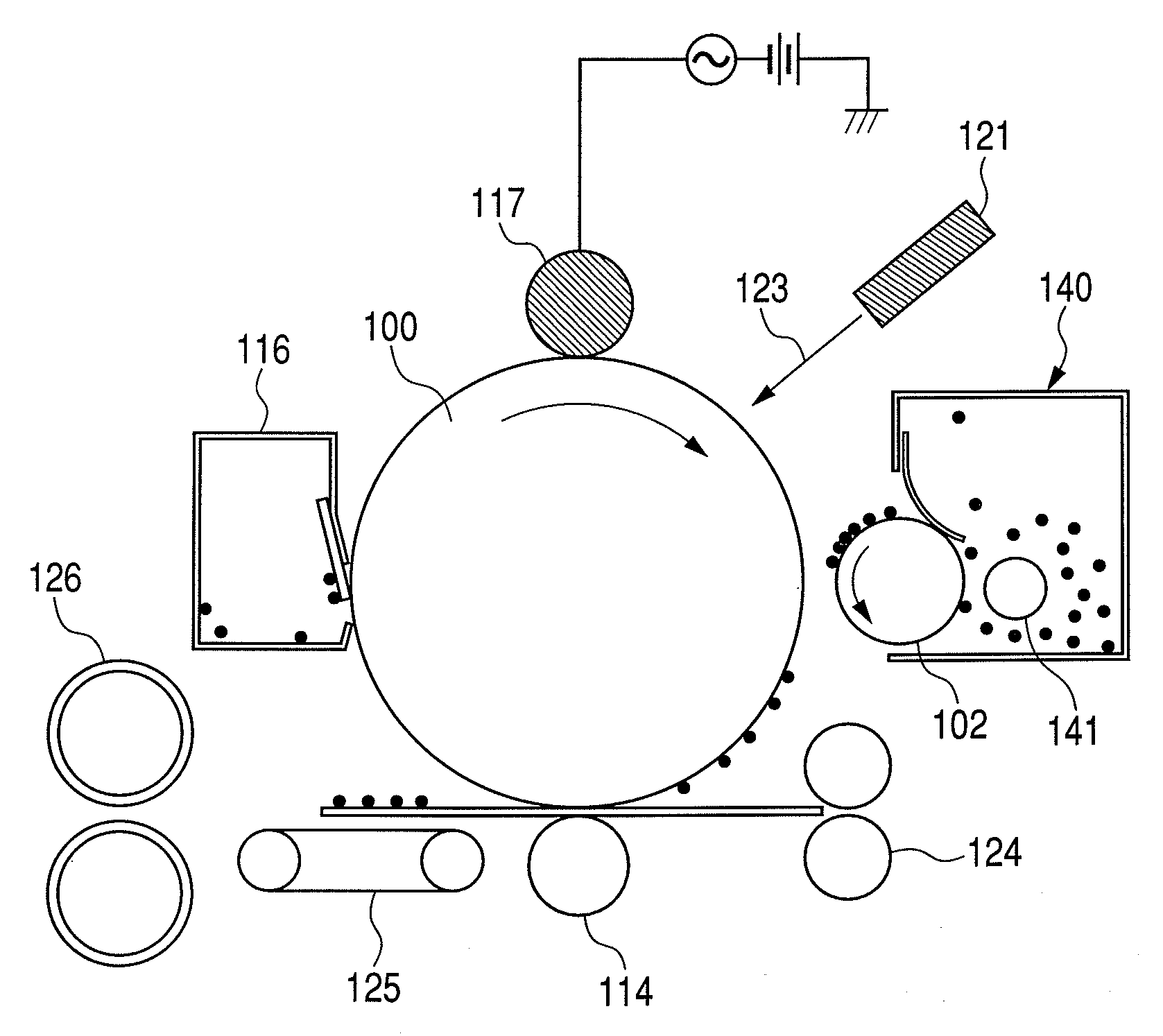
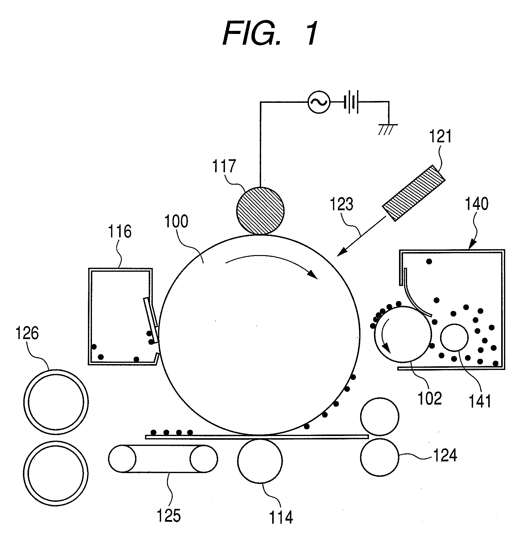
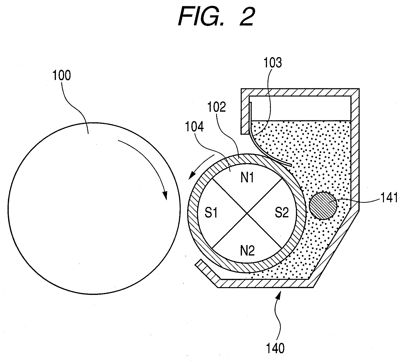
Image

Examples
production example 1
of Magnetic Iron Oxide
[0164]In an aqueous ferrous sulfate solution, a sodium hydroxide solution (containing 1% by mass of sodium hexametaphosphate in terms of P based on Fe) was mixed in an equivalent weight of from 1.0 or more to 1.1 or less based on iron ions, to prepare an aqueous solution which contained ferrous hydroxide. Maintaining the pH of the aqueous solution at 9, air was blown into it to effect oxidation reaction at 80° C. or more to 90° C. or less to prepare a slurry fluid from which seed crystals were to be formed.
[0165]Next, to this slurry fluid, an aqueous ferrous sulfate solution was so added as to be in an equivalent weight of from 0.9 or more to 1.2 or less based on the initial alkali content (the sodium component in the sodium hydroxide). Thereafter, maintaining the pH of the slurry fluid at 8, oxidation reaction was carried on while air was blown into it. At the termination of the oxidation reaction, the pH was adjusted to about 6, and then as silane coupling ag...
production examples 2 to 9
of Magnetic Iron Oxide
[0166]Magnetic Iron Oxides 2 to 9 were obtained in the same way as the above except that, as shown in Table 6, the type(s) of the treating(s) was / were changed and added in the amount(s) shown therein. Physical properties of the magnetic iron oxides obtained are shown in Table 6.
production example 10
of Magnetic Iron Oxide
[0167]Magnetic Iron Oxide 10 as shown in Table 6 was obtained in the same way as in Magnetic Iron Oxide Production Example 1 except that no silane coupling was added.
Production of Magnetic Toner 1
[0168]Into 709 parts by mass of ion-exchanged water, 451 parts of an aqueous 0.1 mol / liter Na3PO4 solution was introduced, followed by heating to 60° C. Thereafter, 67.7 parts of an aqueous 1.0 mol / liter CaCl2 solution was slowly added thereto to obtain an aqueous medium containing Ca3(PO4)2.
[0169]Meanwhile, materials formulated as below were uniformly dispersed and mixed by means of an attritor (manufactured by Mitsui Miike Engineering Corporation).
Styrene74 partsn-Butyl acrylate26 partsSaturated polyester resin 3 parts
(monomer make-up: bisphenol-A propylene oxide addition product / terephthalic acid / isophthalic acid; acid value: 12 mgKOH / g; Tg (glass transition temperature): 69° C.; Mn (number-average molecular weight): 4,200; Mw (weight-average molecular weight): 11,0...
PUM
| Property | Measurement | Unit |
|---|---|---|
| Temperature | aaaaa | aaaaa |
| Percent by mass | aaaaa | aaaaa |
| Frequency | aaaaa | aaaaa |
Abstract
Description
Claims
Application Information