Substrate processing apparatus

a processing apparatus and substrate technology, applied in the field of substrate processing apparatus, can solve the problems of increasing the temperature distribution over the substrate, difficult to maintain the uniformity of etching rate, increasing apparatus cost, etc., and achieve stable processing and efficient and uniform cooling or heating portions.

Active Publication Date: 2009-08-06
CANON ANELVA CORP
View PDF8 Cites 178 Cited by
  • Summary
  • Abstract
  • Description
  • Claims
  • Application Information

AI Technical Summary

Benefits of technology

[0012]This invention has been accomplished in order to solve these problems. That is, the object of this invention is to realize a heat exchanger which efficiently and uniformly cools or heats portions to be maintained at a predetermined temperature, and then to provide a substrate processing apparatus which can continuously carry out stable processing, by disposing the heat exchanger in a substrate holder, a gas emitting mechanism, or a process chamber wall.
[0015]Thus, by arranging the fins on each of two plates and then fixing two plates together so that each fin on one plate may come in between two fins on another plate, a heat exchanger having a high-density fin configuration inside the channel can be realized. The heat exchanger thus constructed remarkably improves the heat transfer, and then the controllability of temperature and the uniformity of temperature over whole surface. If such a heat exchanger is used for a substrate holder, a gas emitting means and the like of substrate processing apparatus, the uniformity and the stability of processing can be greatly improved. Furthermore, a fluid circulating pump and a thermostatic bath can be made compact, resulting in the cost reduction of whole apparatus.
[0017]Moreover, the fin arranged on one plate of said two plates is preferably overlapped with that arranged on another plate, as seen from the perpendicular direction to the flow direction of fluid. This configuration further improves the heat transfer. Then, since the fluid channel is not completely separated by the fins (that is, the fins are not connected to another plate), the fluid can move among respective sub-channels divided by the fins. Therefore, the temperature uniformity can be obtained even when each sub-channel has a different conductance.

Problems solved by technology

However, when semiconductor devices such as LSI are requested to have the higher density and the higher degree of integration to a design rule of 0.13 μm, the cooling capacity of cooling mechanism became insufficient and caused to increase the temperature distribution over the substrate, and made it difficult to maintain the uniformity of etching rate.
However, this method increases the loads of a coolant pump and, for example, a chiller of thermostatic bath, resulting in cost rise of apparatus.
However, when the spacing becomes small to a certain degree, a cutting tool cannot enter into the groove between the fins.
That is, the fin structure wherein the spacing is less than the width of cutting tool has not been able to be fabricated and in other words the higher fin density has been actually impossible.
The fins were not aligned precisely, which caused the non-uniform flow.
Thus, the temperature distribution became non-uniform over the whole substrate surface to deteriorate the etching characteristics and its uniformity.

Method used


Image

  • Substrate processing apparatus
  • Substrate processing apparatus
  • Substrate processing apparatus

Examples


first embodiment

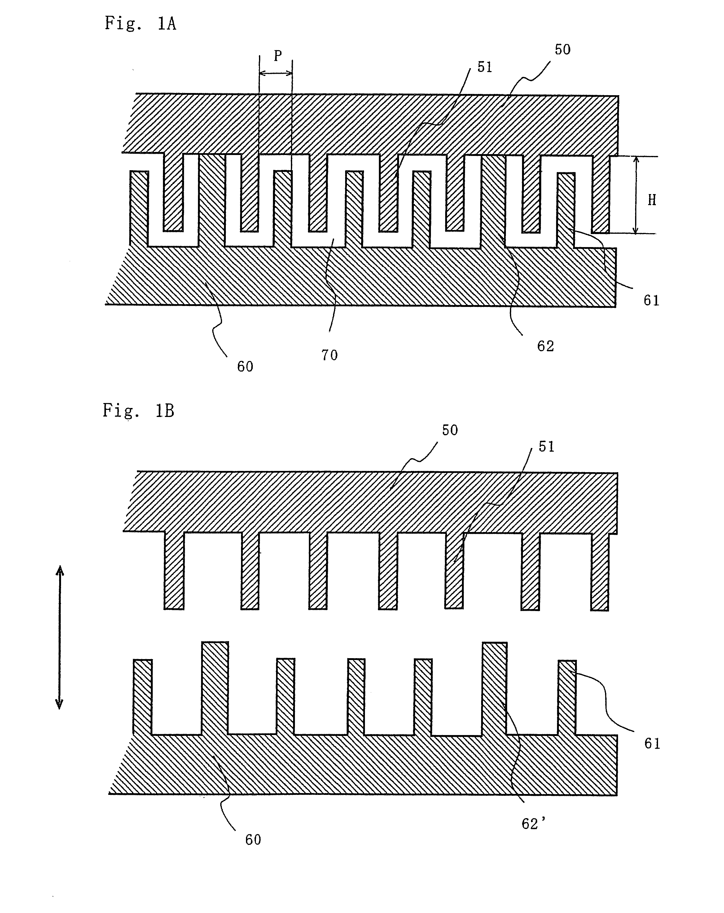
[0029]this invention is shown in FIG. 1. FIG. 1 is a schematic sectional view showing a part of heat exchanger used for a substrate processing apparatus of this invention.

[0030]In a heat exchanger shown in FIG. 1A, the space between two plates 50, 60 is divided with partition walls (fluid channel walls) 62 to form a fluid channel 70. A fluid introduction port and an exhaust port (not illustrated) are disposed at respective ends of the fluid channel. Moreover, a lot of fins 51, 61 are arranged on upper plate 50 and lower plate 60 inside the channel.

[0031]The height of the fin is set so that the ends of upper plate fins 51 and the lower plate fins 61 overlap each other. The inside of channel is not separated completely by the upper plate fins 51 or the lower plate fins 61 so that the fluid moves between sub-channels formed by the fins. The cooling capacity can be made uniform over the entire heat exchanger even when each sub-channel has a different conductance.

[0032]Here, there is no ...

second embodiment

[0055]this invention is shown in FIGS. 2 and 3.

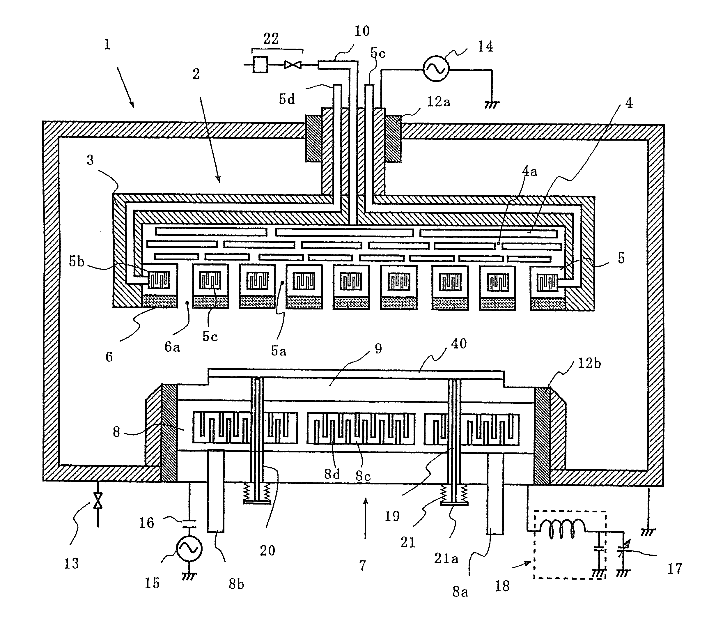
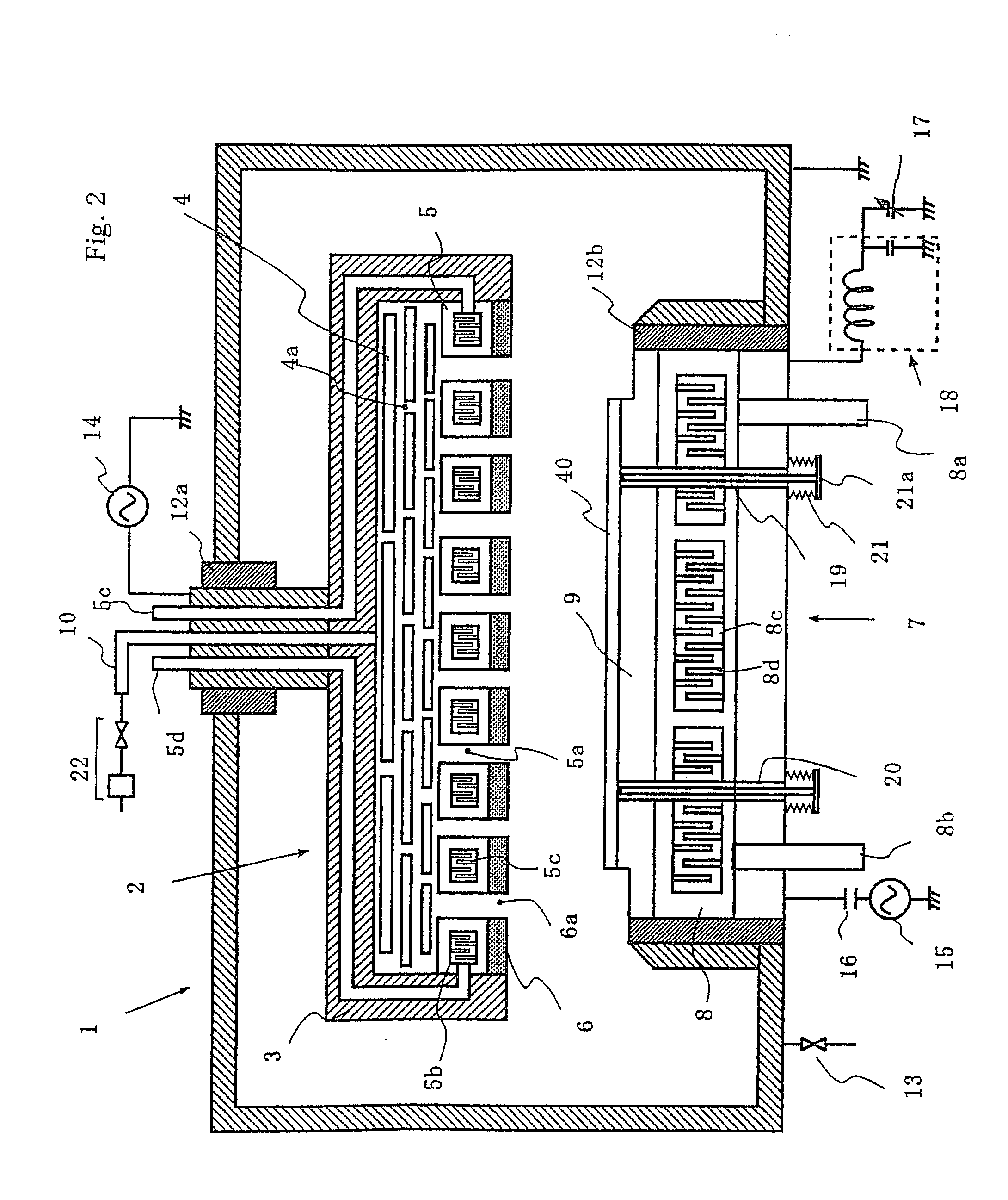
[0056]FIG. 2 is a cross sectional view showing an example of etching apparatus of this invention. As shown in FIG. 2, an opposite electrode (gas emitting means) 2 and a substrate holding electrode (substrate holder) 7 for holding a substrate 40 are arranged facing each other, and are fixed through insulators 12a and 12b in a process chamber 1 of etching apparatus, respectively. The inside of the process chamber is connected with an exhaust means (not illustrated) through a valve 13. The opposite electrode 2 is connected with a first high frequency power source 14 for generating plasma as well as with a gas introduction means comprising a gas introduction pipe 10 and a gas supply system 2 which is composed of a gas cylinder, a mass flow controller, a stop valve and the like.

[0057]The opposite electrode 2 comprises; a gas distribution mechanism in which one or a plurality of gas distribution plates 4 having a number of small holes 4a are ...


PUM

PropertyMeasurementUnit
temperatureaaaaaaaaaa
angleaaaaaaaaaa
fin heightaaaaaaaaaa

Abstract

A method of using a heat exchanger efficiently and uniformly to cool or heats portions to be controlled to a prescribed temperature, and then continuously carry out stable processing. The heat exchanger is constructed by arranging partition walls between two plates to form a fluid channel and a fin parallel with the channel or inclined by a prescribed angle on each of the two plates insides the channel so that the plate or a member in contact with the plate is cooled or heated with the fluid flowing through the channel.

Description

CROSS-REFERENCE TO RELATED APPLICATIONS[0001]This application claims the benefit of Japanese Patent Application No. 2002-054863, filed on Feb. 28, 2002, in the Japanese Intellectual Property Office, and is a continuation application of U.S. application Ser. No. 10 / 375,349, filed Feb. 28, 2003, the entire contents of which are incorporated herein by reference.BACKGROUND OF INVENTION[0002]1. Technical Field[0003]The present invention relates to a substrate processing apparatus and, more particularly, to a semiconductor processing apparatus equipped with a heat exchanger having an excellent temperature control performance.[0004]2. Related Art[0005]A substrate, an opposite electrode, a target and the like in plasma processing apparatuses such as a sputtering apparatus or an etching apparatus used for manufacturing a semiconductor device or a liquid crystal display panel are heated by the plasma or the ion bombardment. Therefore, in order to prevent a temperature rise and perform stable ...

Claims


Application Information

Patent Timeline
Patent Type & Authority Applications(United States)
IPC IPC(8): H01L21/3065H01L21/30F25D9/00C23C16/46C23F4/00H01L21/00
CPCH01L21/67109H01L21/67017H01L21/3065
Inventor SAGO, YASUMIIKEDA, MASAYOSHIKANEKO, KAZUAKIOKADA, TAKUJI
Owner CANON ANELVA CORP
Why Eureka
Try Eureka