Power transmission tool and system

a technology of power transmission and power tool, applied in the direction of motor/generator/converter stopper, dynamo-electric converter control, shape/form/construction, etc., can solve the problems of not producing arcs during operation, requiring a large amount of power to complete the necessary work, and limited tools in their ability to transmit large amounts of power

Inactive Publication Date: 2009-08-13
ATLAS DYNAMIC DEVICES
View PDF22 Cites 28 Cited by
  • Summary
  • Abstract
  • Description
  • Claims
  • Application Information

AI Technical Summary

Benefits of technology

[0023]It is, accordingly, an object of the invention to provide a power tool and system which can deliver a combination of speed and torque for an extended period of time, to st

Problems solved by technology

However the tools are limited in their ability to transmit large amount of power for an extended period of time due to the finite amount of energy in the battery.
These motors do not employ carbon brushes and a rotating commutator to function thereby.
Therefore, they do not produce any arc during operation.
However this type of motor is controlled with a computer and an electronic switching circuit which characteristically produces a signature of electromagnetic interference (EMI).
These applications often require a large amount of power to complete the necessary work.
Starting and stopping such a mass with a power driver such as a compressed air powered ratchet wrench, causes an adverse reaction to the operator.
This reaction may result in a large force reaction which the operator must counteract.
Some such applications for high power requirements are subject to exposure to potentially dangerous fluids and gasses such as on an aircraft carrier or in an aircraft hanger.
Additionally, these applications may be exposed to salt spray and rain.
Lui however is limited to dissipating heat to the outside through one end of the motor enclosure which is necessarily limited in surface area and consequentially ma

Method used


Image

  • Power transmission tool and system
  • Power transmission tool and system
  • Power transmission tool and system

Examples


Embodiment Construction

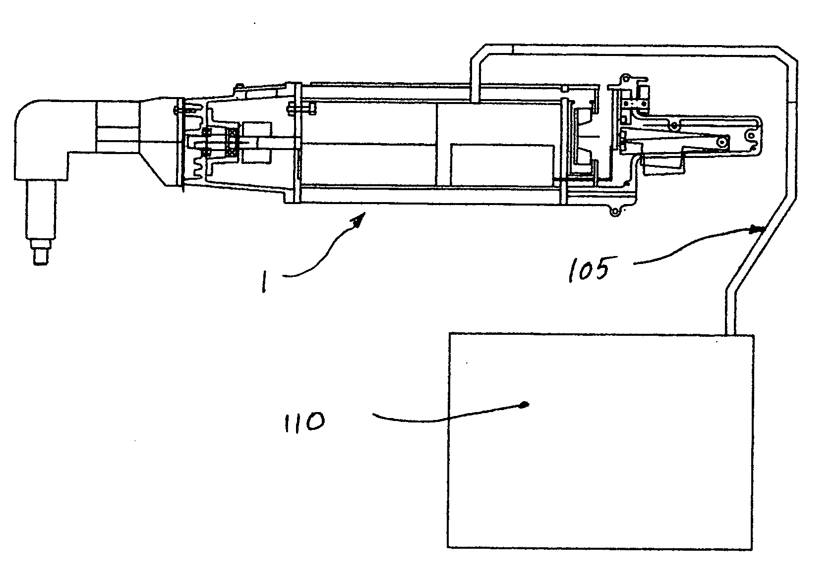
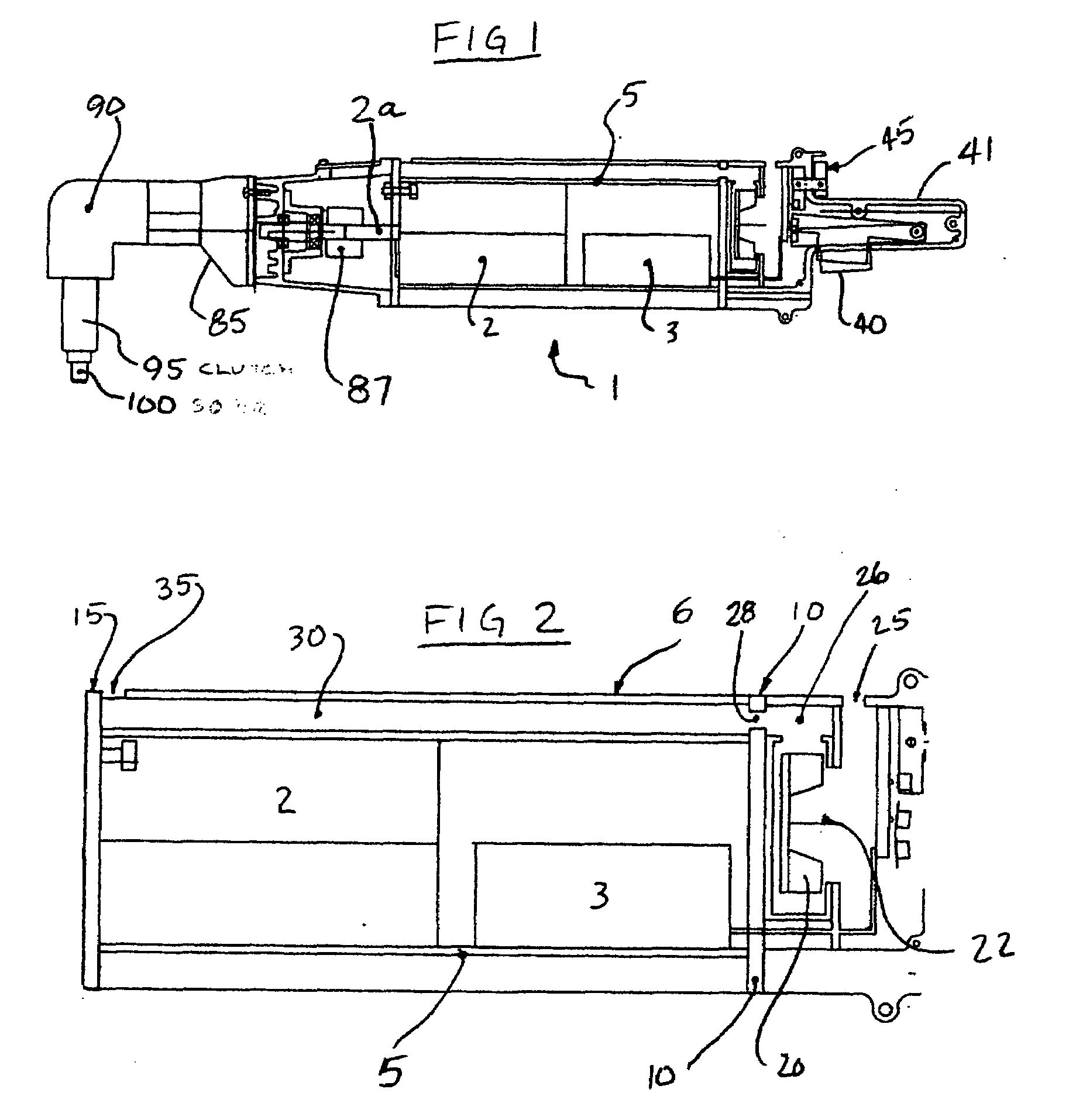
[0044]As described below, a power transmission tool and system, designed for intrinsically safe operation, may include a brushless or sparkless motor, speed reducing means, a power controller, an arcless or sparkless power switch and motor direction switch, a right angle power transmission means, a torque limiting clutch, a power transmission coupling means, and heat transfer means are housed in a “L” shaped housing which has a human interface ergonomic handle to manage the forces due to torque transmission, and with a detachable power cable and an exterior power supply box.

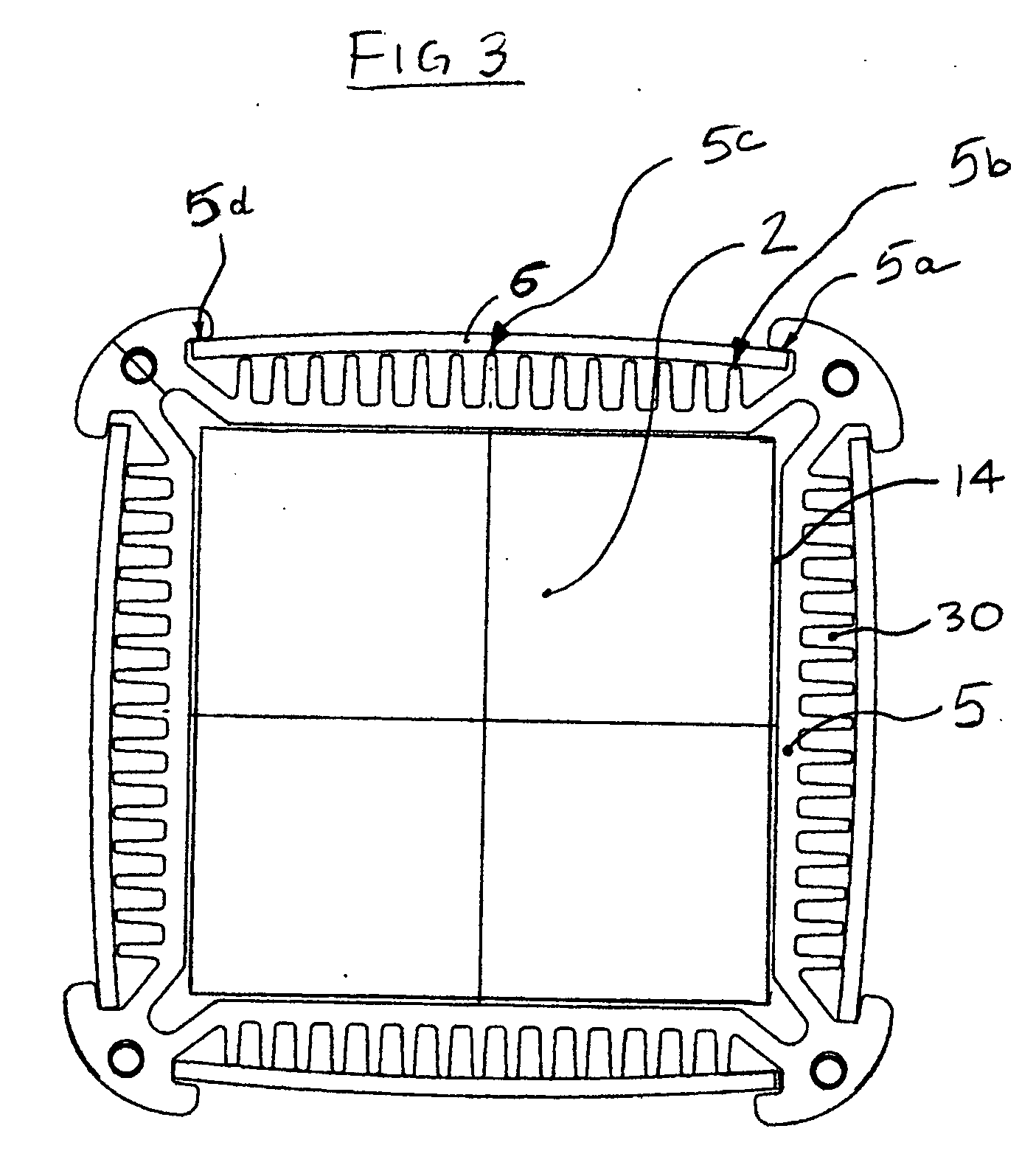
[0045]The motor and controller are encased in a sealed housing which has external cooling fins and end plates which are sealably attached to the first end and second end of the motor housing. The speed reducing means may be a train of gears of the parallel axis or planetary design. The housing of the gears may be sealed to prevent water or dust ingress.

[0046]The lower speed shaft from the speed reducing means is ...


PUM


Abstract

An improved power tool system includes a power tool and an external power supply connected via a cable to provide utility and safety in a hazardous operation such as loading ammunition into a weapon in an environment of flammable materials and extreme environmental exposure. The power tool includes a sparkless motor, a sparkless controller and sparkless switches, in a sealed enclosure with improved heat transfer means. The power tool has improved torque controlling means to mitigate reaction torque to the operator and equipment when starting or stopping highly inertial loads. A sealed enclosure is provided to prevent liquids from entering the motor and controller cavity and includes a thermally conductive path to conduct heat from the motor and controller through the enclosure to cooling fins and a coolant path formed between the fins and an entrapment wall.

Description

CROSS REFERENCE TO RELATED APPLICATIONS[0001]This application claims the benefit of Provisional patent application Ser. No. ______BACKGROUND OF THE INVENTION[0002]This invention relates to a power tool which may be used in and around environments which may be exposed to flammable substances while providing a configuration which is conducive for the operator to handle while transmitting high torque to the application.[0003]Historically, power tools have been made to be lightweight yet provide a high level of power yielding a high power density. This was achieved by utilizing a type of motor called a universal motor.[0004]A universal motor requires carbon brushes to transmit and commutate electricity to the rotating armature. The universal motor typically employs an air moving fan to move air through the motor housing to exhaust the heat from the motor. These motors typically operate at mains voltage supplies from roughly 10V AC to 240V AC.[0005]Typically, power tools of this type use...

Claims


Application Information

Patent Timeline
IPC IPC(8): H02K7/14H02K9/00H02K5/12H02H7/08
CPCH02K5/136H02K9/14H02K5/18
Inventor WALTER, RICHARD THOMAS
Owner ATLAS DYNAMIC DEVICES
Why Eureka
Try Eureka