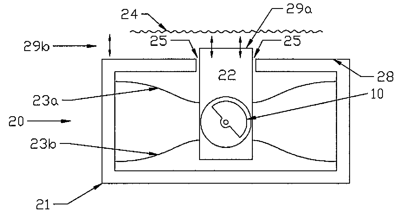
[0021]Accordingly, embodiments according to aspects of the present invention provide a novel implementation of a low-cost, wide-bandwidth vibrotactile transducer employing an EM motor. In some embodiments, the EM motor forms part of the moving mass of the transducer actuator, or mechanical
contactor. The moving mass is in contact with a
skin (body) load. The moving mass may be constrained into approximately
vertical motion (perpendicular to the
skin surface) by a spring between the actuator housing and moving mass. The rotational forces provided by an eccentric mass (EM) motor may therefore be limited to predominantly one dimensional motion that acts perpendicularly against a skin (body) load. The contacting face of the actuator housing may be in simultaneous contact with the body load (skin). The body load, actuator moving mass, spring compliance and housing mass make up a moving mass resonant
system. The spring compliance and system component masses may be configured to maximize the actuator displacement while minimizing the housing motion and to tailor the transducer response to a desired level.
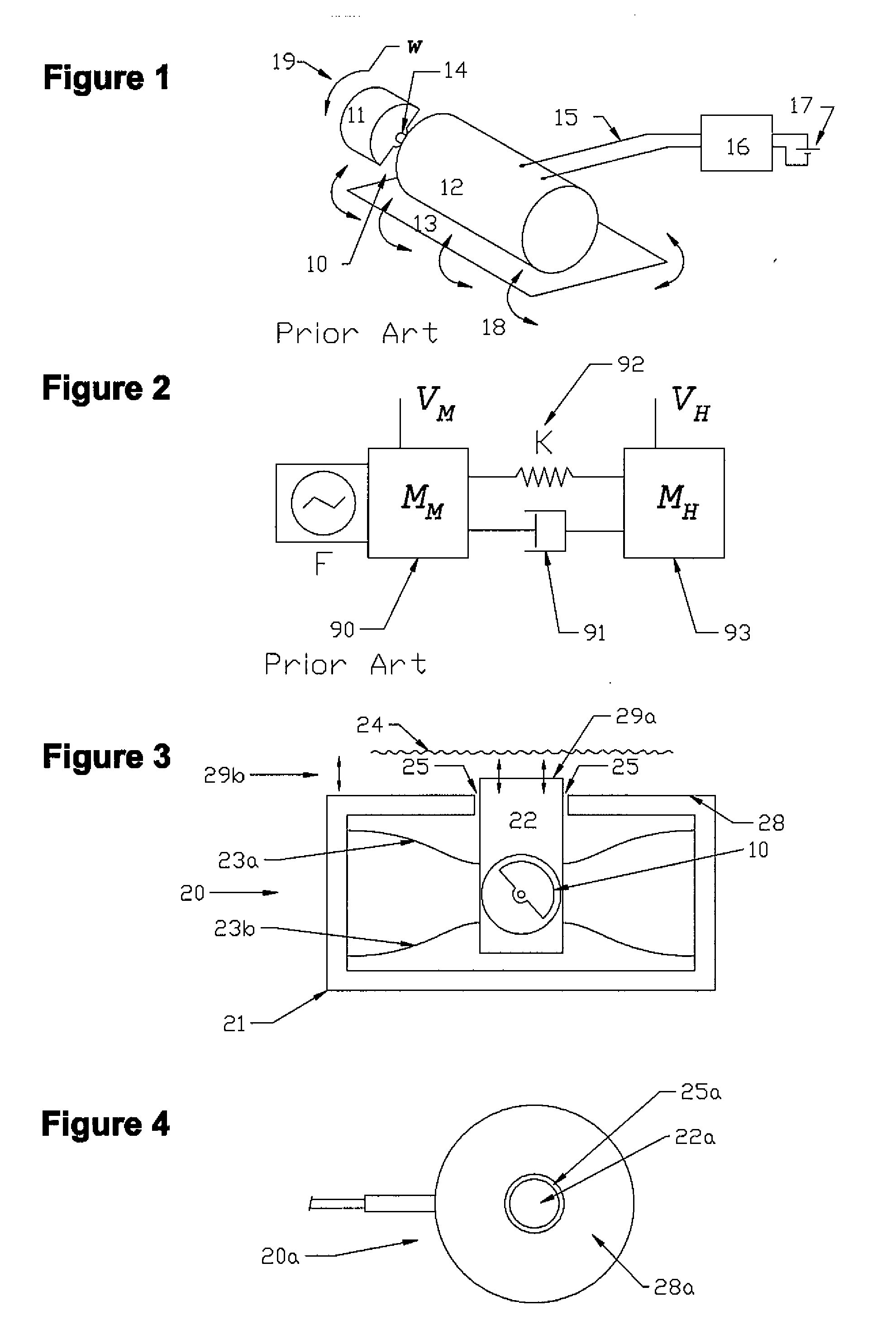
[0022]For
wide band operation, the spring compliance may be chosen together with the system component masses, loading and dimensions, such that the
resonance occurs at or below the desired
operating frequency, typically operating the transducer at frequencies above
resonance. An EM motor produces an inertial force proportional to the size of the eccentric mass and the rotational velocity squared. In one embodiment, the EM motor force generator is combined with a mass-spring mechanical resonant oscillator as a transducer configuration. The mechanical oscillator is a well known combination of at least one moving mass and a spring. When operating above the mechanical oscillator
resonance frequency, the moving mass characteristic velocity attenuates proportional to frequency. This results in a beneficial shaping of the EM motor force characteristics and an overall system displacement response that is relatively flat over a wide
operating frequency range.
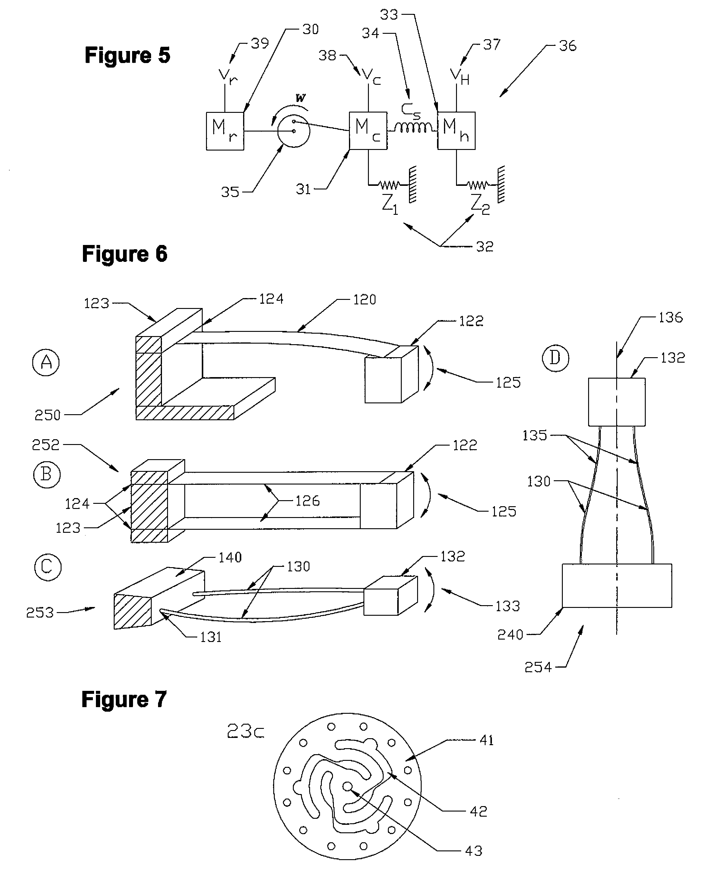
[0023]This configuration may, for example, be implemented as a
low mass wearable vibrotactile transducer, as a haptic push-button or touch screen display, or as a transducer that is mounted within a soft material such as a seat or within the in-sole of a shoe, and is intended to convey vibration to the body adjacent to the transducer. A particular
advantage of this configuration is that the moving mass motion can be made almost independent of force loading on the transducer housing.
[0024]The method and apparatus for generating a vibrational stimulus of this invention provides an improved small, low cost vibrotactile transducer to provide a controllable strong tactile stimulus that can be easily felt and localized by a user involved in various activities, for example driving a car, flying an aircraft, playing a
video game, walking, interacting with a display, or performing an industrial
work task. Due to the
high amplitude and point-like
sensation of the vibrational output, the inventive vibrotactile transducer (“tactor”) can be felt and localized at various positions on the body, and can provide information to the user. The transducer itself may be a small
package that can easily be located against the body when installed under or on a garment, or on the seat, within an insole,
display device, or back of a chair. The drive
electronics are compact, able to be driven by batteries, and follows conventional motor driver control techniques. The overall transducer may include interface circuitry that is compatible with digital (e.g., TTL,
CMOS, or similar) drive signals typical of those from external interfaces available from computers,
video game consoles, and the like.
[0026]Therefore, embodiments according to aspects of the present invention may provide a new and
improved method and apparatus for generating a wide-band vibrational stimulus to the body of a user. Embodiments may further provide a new and improved low cost vibrotactile transducer and associated drive controller
electronics. Embodiments may also provide a new improved eccentric mass motor transducer that has a vibrational displacement output that is substantially uniform in transducer displacement over a wide
frequency band of interest. Other embodiments may provide a new and improved transducer that is integrated into the mechanism of a
push button switch or screen display, to provide enhanced haptic and tactile information to the finger or hand of a user. Further embodiments may provide a new and improved transducer that can easily be located against the body when installed under or on a garment, within the insole of a shoe, or on the seat or back of a chair.

